[0022] The following descriptions are only preferred embodiments embodying the principles of the present invention, and do not limit the protection scope of the present invention
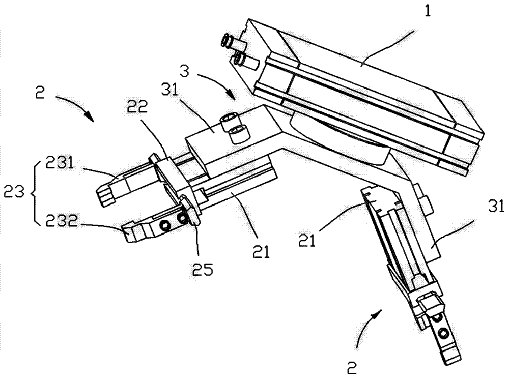
 accordingly
[0023] Such as Figure 1 to 2 Shown is an embodiment of the loading and unloading mechanism of the present invention, which includes a rotating cylinder 1, a mounting plate 3 is fixed on the rotating part of the rotating cylinder (1), and both ends of the mounting plate 3 are bent to form There are two bent plate parts 31, the two bent plate parts 31 form an included angle of 90°, and the two bent plate parts 31 are respectively installed with a tool clamping mechanism 2;
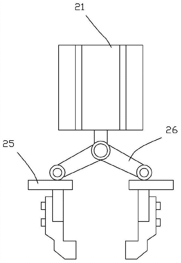
[0024] The structure of the tool clamping mechanism 2 includes a driving cylinder 21 and a guide rail part 22. The clamping part 23 is movably mounted on the guide rail part 22, and the clamping part 23 is driven by the piston rod of the driving cylinder 21.
[0025] In this embodiment, the clamp part 23 is composed of a left clamp 231 and a right clamp 232. The left clamp 231 and the right clamp 232 are respectively fixed on a sliding part 25, and the sliding part 25 is movably mounted on Rail component 22 is on.
[0026] In this embodiment, the left clamp 231 and the right clamp 232 are respectively connected to the piston rod of the driving cylinder 21 through the connecting rod 26. The front ends of the two connecting rods 26 are hinged on the piston rod of the driving cylinder 21, and the rear ends are respectively connected to the piston rod of the driving cylinder 21. The left clamp 231 and the right clamp 232 are hinged.
[0027] In this embodiment, the guide rail member 22 is provided with a dovetail groove 221, the sliding member 25 has a T-shaped structure, the rear end of the sliding member 25 is matched with the dovetail groove 221, and the front end of the sliding member 25 is connected to the clamp part. 23 fixed together.
[0028] In this embodiment, the clamp part 23 is symmetrically mounted on the rail member 22 by the left clamp 231.
[0029] In this embodiment, the sliding member 25 is symmetrically mounted on the rail member 22.
[0030] In this embodiment, the inner sides of the front ends of the left clamp 231 and the right clamp 232 are provided with a notch 233 that cooperates with the cutter when clamping the cutter.
[0031] In this embodiment, the driving cylinder 21 is fixed to the bent plate portion 31 of the mounting plate body 3 by a hexagon socket bolt.
[0032] In this embodiment, the guide rail member 22 is fixed to the front end of the driving cylinder 21 by a hexagon socket bolt.
[0033] In this embodiment, the left clamp 231 and the right clamp 232 are fixed on the sliding member 25 by hexagon socket bolts.
[0034] When the present invention is working, the left clamp 231 and the right clamp 232 are driven by the driving cylinder 21. More specifically, when the piston rod of the driving cylinder 21 extends, the piston rod pushes the connecting rod 26, and the connecting rod 26 drives the left The clamp 231 and the right clamp 232 are opened, and when the piston rod of the driving cylinder 21 is retracted, the connecting rod 26 drives the left clamp 231 and the right clamp 232 to close together, and the tool to be ground is clamped in In the notch 233, because the two bent plate portions 31 have an included angle of 90° during operation, the two tool clamping mechanisms 2 installed on the bent plate portion 31 when one of the tool clamping mechanisms 2 is in a horizontal position The other tool clamping mechanism 2 is located in the vertical direction, and the left clamp 231 and the right clamp 232 of the tool clamping mechanism 2 located in the vertical direction clamp the unground tool to take the material from the feeding tray, and The tool clamping mechanism 2 in the horizontal position clamps the finished tool to remove the tool from the working head, and then rotates the rotating part of the air cylinder 1 to realize the position swap of the two tool clamping mechanism 2. Open the left clamp 231 and the right clamp 232. At this time, the tool clamping mechanism 2 located in the vertical direction will place the finished tool on the feeding tray, while the tool clamping mechanism 2 located in the horizontal position will not The grinding tool is clamped to the working head, and the loading and unloading is quick and convenient, which greatly improves the work efficiency.
[0035] Such as image 3 Shown is an embodiment of a rotating upper tray, which includes a chassis 91 on which a tray 92 is placed and positioned by a positioning pin 911, a central hole 923 is opened on the tray 92, and a quick clamp 93 Fixed on the chassis 91 and located in the central hole 923 of the material tray 92, the pressing head of the quick clamp 3 is pressed against the material tray 92, and the material tray 92 is provided with a number of inserts for placing knives Jack 921.
[0036] In this embodiment, the material tray 92 is provided with a pin hole 922, the chassis 91 is provided with a positioning pin 911, and the positioning pin 911 cooperates with the pin hole 922 to realize the positioning of the material tray 92 and the chassis 91. Specifically, in this embodiment In the example, the number of the positioning pin 911 is one, the pin hole 922 is perforated, and the positioning pin 911 and the pin hole 922 cooperate to achieve positioning, and can be placed in place when the tray 92 is removed and then reinstalled.
[0037] The number of jacks 921 can be set according to specific needs. Specifically, in this embodiment, there are a total of 960 jacks 921. The jacks 921 are counterbores opened on the tray 92, and the jacks 921 are in a circular array. Distributed on the material tray 92, a cutter can be inserted into each socket 921.
[0038] In this embodiment, the material tray 92 and the chassis 91 are made of steel, and the head of the positioning pin 911 is in a sharp wedge shape, and the positioning pin 911 can be inserted into the pin hole 922 more conveniently.
[0039] Such as Figure 4 As shown, the working steps of rotating the upper tray are:
[0040] The chassis 91 is driven to rotate by a servo motor 94, and the servo motor 94 is controlled by a numerical control system. A chuck such as an automatic robotic arm picks up parts and returns to the original position after the tool grinding is completed, and then the servo motor 94 rotates An index enters the position of the next hole 921, and then the chuck removes the unground tool, and the work is repeated. Below the chassis 91 is provided an induction probe 95 for the reset of the servo motor 94. The induction probe 95 is also Connected with the numerical control system, it is convenient for the material tray 92 to rotate back to the initial position.
[0041] The present invention can open the quick clamp 93 to remove the material plate 92 after all the tools on the material tray 92 are ground, and then take out all the grinding tools and replace them with unground tools, which is very convenient for loading and unloading , Which speeds up the tool feeding speed, and further improves the efficiency of CNC tool sharpening.