Movable ceramic tile laying machine

A mobile tile technology, applied in construction, building construction, etc., can solve the problems of high labor intensity and time-consuming tile laying, and achieve the effects of shortening the time of laying tiles, convenient operation, and reducing labor intensity

Active Publication Date: 2015-07-15
NANTONG CHENGSHAN CONSTR ENG
View PDF6 Cites 31 Cited by
  • Summary
  • Abstract
  • Description
  • Claims
  • Application Information

AI Technical Summary

Problems solved by technology

[0003] In order to solve the problem of high labor intensity and time-consuming tile laying in the prior art, the present invention aims to provide a mobile tile laying machine, which is equipped wit

Method used


Image

  • Movable ceramic tile laying machine
  • Movable ceramic tile laying machine

Examples


Embodiment Construction

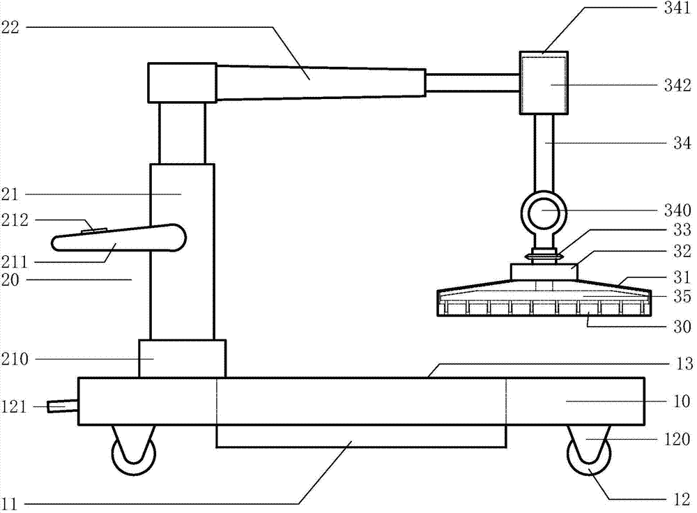
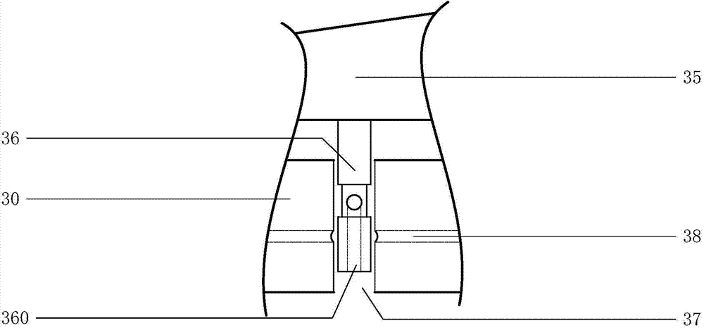
[0016] See attached figure 1 and combine figure 2 , The mobile tile laying machine of this embodiment includes a mobile frame 10, a suction cup control frame 20 and a tile suction cup 30, the mobile frame 10 is a box-shaped structure and is provided with a multi-port hydraulic press 11 and mobile rollers 12, The suction cup control frame 20 is installed on the tail of the mobile frame 10 and its structure includes a vertical lifting frame 21 and a horizontal telescopic arm 22. The vertical lifting frame 21 is provided with a rotating base 210 and a control handle 211. The horizontal telescopic The arm 22 is installed on the top of the vertical lifting frame 21. The bottom surface of the ceramic tile sucker 30 is flat and smooth and the top is provided with a cover-type housing 31, and the top of the cover-type housing 31 is provided with a sand ash vibrator 32, a ring-shaped ray gun 33 and Suspension rod 34, in the middle and top of the suspension rod 34 are respectively pro...


PUM


Abstract

The invention discloses a movable ceramic tile laying machine which comprises a movable rack, a sucker control frame and a ceramic tile sucker, wherein the movable rack is of a box-type structure and is provided with a multi-port hydraulic press and moving rollers; the sucker control frame is arranged at the tail of the movable rack and structurally comprises a vertical lifting frame and a transverse telescopic arm; the bottom surface of the ceramic tile is flat and smooth; a hood-type casing is arranged at the top of the ceramic tile sucker; a sand dust vibrator, a round ray gun and a suspension hanging rod are arranged at the top of the hood-type casing. According to the embodiment, ceramic tiles are carried by using a negative pressure attraction principle; sand dust on the bottom surfaces of the ceramic tiles is tempered and flattened by the sand dust vibrator; the ceramic tiles are laid to set horizontal positions by the round ray gun; a decoration worker can flatly and firmly lay the ceramic tiles on the ground by gripping a control handle by hand and controlling a keyboard; therefore the movable ceramic tile laying machine is reasonable in structure and convenient for control; the laying time of the ceramic tiles by the decorating workers can be shortened, and the labor intensity of the decorating workers can be reduced.

Description

technical field [0001] The invention belongs to a mechanical device, in particular to a mobile tile laying machine. Background technique [0002] In the process of laying floor tiles, the decoration workers first spread a layer of relatively dry cement sand ash with a thickness of about 3 cm on the ground, and then spread the tiles on the top surface of the dry sand ash and repeatedly tap the tiles with a rubber hammer. The knocking force will tamp the sand and ash on the bottom of the tiles. When the sand and ash are compacted and relatively flat, the tiles will be moved away. The sand and ash will be leveled according to the traces of the vibration of the tiles, and then the tiles will be laid on the top of the sand and ash again. Repeated tamping and leveling work on the surface, the sand and ash on the ground must be tamped into a solid flat surface after repeated tamping and leveling work, and then wet cement is spread on the bottom of the tiles for paving, and the top ...

Claims


Application Information

Patent Timeline
IPC IPC(8): E04F21/22
Inventor 詹国林
Owner NANTONG CHENGSHAN CONSTR ENG
Why Eureka
Try Eureka