Interlayer insulating placement structure for oil-immersed transformer

An oil-immersed transformer, interlayer insulation technology, applied in the direction of transformer/inductor coil/winding/connection, etc., can solve problems such as affecting the overall structure and self-weight of the transformer, unreasonable winding and coil structure design, and increasing the volume of the transformer winding structure. , to achieve the effect of saving raw materials, compact structure and reducing the number of use

Inactive Publication Date: 2015-07-15
华夏恒业智能电气有限公司
View PDF6 Cites 1 Cited by
  • Summary
  • Abstract
  • Description
  • Claims
  • Application Information

AI Technical Summary

Problems solved by technology

At present, in the transformer production industry, 0.08mm cable paper is usually used for use, and the number of sheets of cable paper is generally selected according to the breakdown voltage of 4.75kV / sheet after oil immersion, resulting in the interlayers of each winding coil being composed of multiple layers. The cable paper is used for insulation and isolation, but the traditional winding structure leads to the unreasonable design of the winding coil structure when laying the cable paper, which leads to a large amount of cable paper used when the insulation level is met.
On the one hand, it becomes a waste of cable paper, on the other hand, it also increases the volume of the transformer winding structure, which affects the overall structure and self-weight of the transformer, and also leads to a significant temperature rise and poor heat dissipation effect during the operation of the transformer

Method used


Image

  • Interlayer insulating placement structure for oil-immersed transformer
  • Interlayer insulating placement structure for oil-immersed transformer
  • Interlayer insulating placement structure for oil-immersed transformer

Examples


Embodiment Construction

[0013] In order to make the technical means, creative features, goals and effects achieved by the present invention easy to understand, the present invention will be further described below in conjunction with specific embodiments.

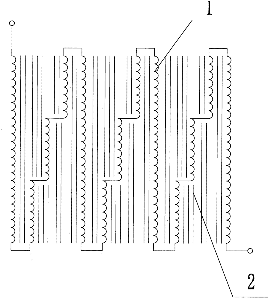
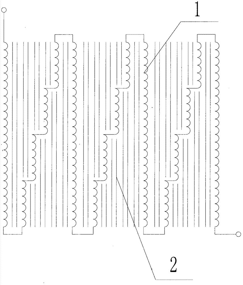
[0014] Such as Figure 1 to Figure 4 , an oil-immersed transformer interlayer insulation placement structure of the present invention, including transformer winding coils 1 and cable paper 2, wherein at least three transformer winding coils 1 are connected in series, and each transformer winding coil 1 is distributed in parallel, and among them The transformer winding coils 1 on both sides are further divided into at least three sections with the same length, and the transformer winding coils 1 of each section are connected in series, and the transformer winding coils 1 are isolated by cable paper 2, and the cable paper 2 is at least two .

[0015] In this embodiment, the number of subsections of the transformer winding coil 1 located in the midd...


PUM


Abstract

The invention relates to an interlayer insulating placement structure for an oil-immersed transformer. The interlayer insulating placement structure comprises transformer winding coils and cable paper, wherein at least three transformer winding coils are connected in series and are respectively distributed in parallel; a part between the transformer winding coils positioned on two sides of the structure is divided into at least three sections of structures with the same length; the transformer winding coils of all the sections are connected in series; all the transformer winding coils are separated by the cable paper; at least two pieces of cable paper are arranged. According to the interlayer insulating placement structure disclosed by the invention, the structure is compact; the use quantity of insulation paper is effectively reduced while operation performance of the transformer is guaranteed, so that on one hand, the effects of saving raw materials and reducing the cost of the transformer are realized, and on the other hand, the structure of the transformer is also effectively simplified, the size and dead weight are reduced, the temperature rise effect of the transformer during operation is reduced, the heat dissipating performance of the transformer is enhanced, and eventually the aim of improving the performance of the transformer is achieved.

Description

technical field [0001] The invention relates to an interlayer insulation placement structure of an oil-immersed transformer, which belongs to the technical field of transformer equipment. Background technique [0002] Cable paper is generally used for interlayer insulation of oil-immersed power transformer winding coils. At present, there are two main specifications of cable paper used: 0.08mm and 0.12mm. In the production of transformers, in order to minimize the types of specifications used for cable paper, it is convenient for procurement and production. At present, in the transformer production industry, 0.08mm cable paper is usually used for use, and the number of sheets of cable paper is generally selected according to the breakdown voltage of 4.75kV / sheet after oil immersion, resulting in the interlayers of each winding coil being composed of multiple layers. The cable paper is used for insulation and isolation, but the traditional winding structure leads to the unr...

Claims


Application Information

Patent Timeline
IPC IPC(8): H01F27/28H01F27/32
Inventor 陈安平李德强张金钟
Owner 华夏恒业智能电气有限公司
Why Eureka
Try Eureka