Vertical full-annular-direction positioning jig frame device system and construction technology for large-diameter pile foundation reinforcement cage

A construction technology and technology for positioning tires, which is applied in the field of pile foundation reinforcement cage auxiliary positioning installation device system and construction technology, can solve the problems of high tire mold processing costs, time-consuming and labor-intensive production, poor economy, etc., and achieve the effect of ensuring dimensional accuracy

Active Publication Date: 2015-07-22
CHINA GEZHOUBA GROUP NO 5 ENG
View PDF9 Cites 18 Cited by
  • Summary
  • Abstract
  • Description
  • Claims
  • Application Information

AI Technical Summary

Problems solved by technology

[0002] The production of the pile foundation reinforcement cage is usually made of ordinary steel plates according to the 1/3 arc of the radius of the reinforcement cage to form a longitudinal reinforcement positioning mold, and the main reinforcement of the laid material is placed in the positioning groove of the mold according to the length configuration, adjusted and aligned. After the installation of 1/3 surface is completed, use a crane to roll over, and then repeat the above steps in order to complete the rema...

Method used


Image

  • Vertical full-annular-direction positioning jig frame device system and construction technology for large-diameter pile foundation reinforcement cage

Examples


specific Embodiment approach

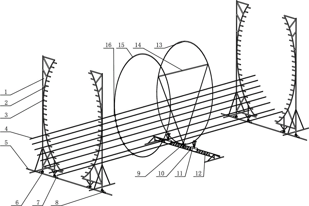
[0039](1) Fabrication and installation of the vertical positioning tire frame 1. The vertical positioning tire frame 1 is made of ordinary threaded steel bars, and two longitudinal reinforcement vertical positioning tire frames 1 that can be butted into the overall circular section of the reinforcement cage are made according to the 1 / 2 arc of the reinforcement cage diameter required by the design; in each reinforcement cage Longitudinal ribs 4 are welded at the designed position, and comb holes 3 are formed with comb-teeth bars 2 made of ordinary threaded steel bars; mobile pulleys 6 are installed at the bottom of vertical positioning tire frame 1; tire frame moving rails 5 are set on the concrete foundation work platform, and vertical Type positioning tire frame 1 is installed on the tire frame moving rail 5.

[0040] (2) Fabrication and installation of the support tire frame 12. Adopt common straight threaded steel bar to make support tire frame 12, select support point an...


PUM


Abstract

The invention relates to a vertical full-annular-direction positioning jig frame device system and construction technology for a large-diameter pile foundation reinforcement cage. The vertical full-annular-direction positioning jig frame device system comprises vertical positioning jig frames and a supporting jig frame, wherein the vertical positioning jig frames are installed on jig frame moving rails. According to the design and arrangement size of longitudinal ribs of the reinforcement cage, comb holes are formed in the vertical positioning jig frames and used for containing the longitudinal ribs of the reinforcement cage, moving sliding wheels capable of moving left and right in the direction of the cross section of the reinforcement cage are installed at the bottoms of the vertical positioning jig frames, the moving sliding wheels are installed on the jig frame moving rails, a fixed supporting clamp and a movable supporting clamp are arranged on the supporting jig frame and used for fixing stiffened stirrups, triangular supporting ribs are installed in the stiffened stirrups and used for improving the strength of the stiffened stirrups, and plate ribs of the reinforcement cage are fixedly installed on the longitudinal ribs of the reinforcement cage at a certain interval through binding wires. Due to the arrangement of the full-annular-direction movable jig frame device, the pile foundation reinforcement cage can be manufactured at a time, and the manufacturing efficiency of the reinforcement cage is greatly improved; besides, machining precision is high, speed is high, the jig frames can be repeatedly used, operation is convenient, and the vertical full-annular-direction positioning jig frame device system and construction technology are economical and fast to use.

Description

technical field [0001] The invention relates to a pile foundation reinforcement cage auxiliary positioning and installation device system and construction technology, in particular to a large-diameter pile foundation reinforcement cage vertical full-circle positioning tire frame device system and construction technology, which belongs to civil construction auxiliary construction device and construction craft. Background technique [0002] The production of the pile foundation reinforcement cage is usually made of ordinary steel plates according to the 1 / 3 arc of the radius of the reinforcement cage to form a longitudinal reinforcement positioning mold, and the main reinforcement of the laid material is placed in the positioning groove of the mold according to the length configuration, adjusted and aligned. After the installation of 1 / 3 surface is completed, use a crane to roll over, and then repeat the above steps in order to complete the remaining part of the construction. ...

Claims


Application Information

Patent Timeline
IPC IPC(8): B21F33/00
Inventor 符强汪少雄吕芝林何贝张涛彭元平雷义文黄明星焦东旺
Owner CHINA GEZHOUBA GROUP NO 5 ENG
Why Eureka
Try Eureka