A wireless measuring device for machine tool cutting force

A wireless measurement and cutting force technology, applied in the direction of measurement/indicating equipment, metal processing machinery parts, metal processing, etc., can solve the problems of current changes, simultaneous and real-time measurement, etc., to reduce additional torque and ensure safe operation , Improve the effect of measurement accuracy

Active Publication Date: 2017-03-29
BEIJING INSTITUTE OF TECHNOLOGYGY
View PDF6 Cites 0 Cited by
  • Summary
  • Abstract
  • Description
  • Claims
  • Application Information

AI Technical Summary

Problems solved by technology

[0005] The above two cutting force measurement methods in the turning-milling composite machining process are mainly used in the experimental research of cutting force measurement in the cutting process of conventional parts. Although the basic function of cutting force measurement has been realized, the two methods still have the following problems: Disadvantages: Indirect measurement method Since the feed motor of the machine tool will have a corresponding current change only when there is feed motion in the corresponding direction, only the cutting force in the feed direction can be measured by this method, so This indirect measurement method cannot simultaneously and real-time measure the grinding force on the workpiece in three directions; the local wireless measurement method is limited by its own installation method, and most of the cutting force on the workpiece is borne by the installation mechanism , only a small part of the cutting force is transmitted to the sensor for measurement, which leads to the fact that the cutting force measured by the sensor is not a 100% true reflection of the actual force situation, and the measurement results have certain limitations

Method used


Image

  • A wireless measuring device for machine tool cutting force
  • A wireless measuring device for machine tool cutting force
  • A wireless measuring device for machine tool cutting force

Examples


Embodiment Construction

[0027] The present invention will be described in detail below with reference to the accompanying drawings and examples.

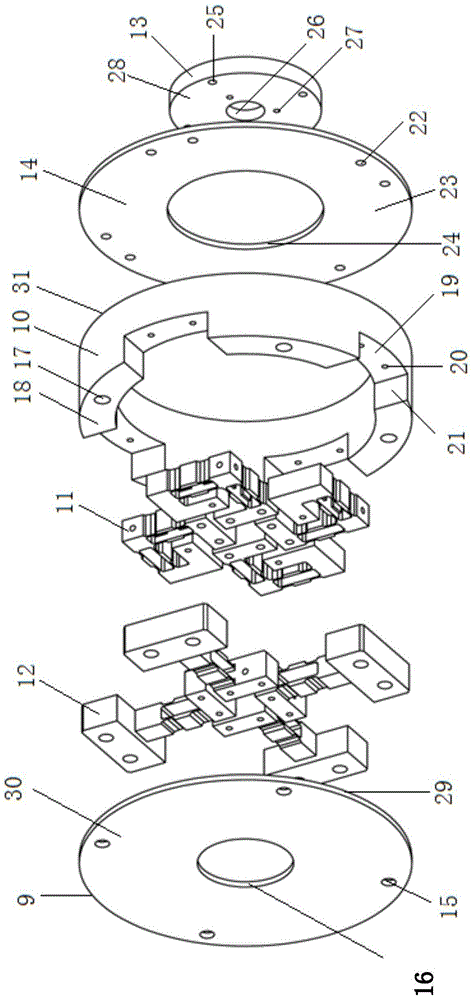
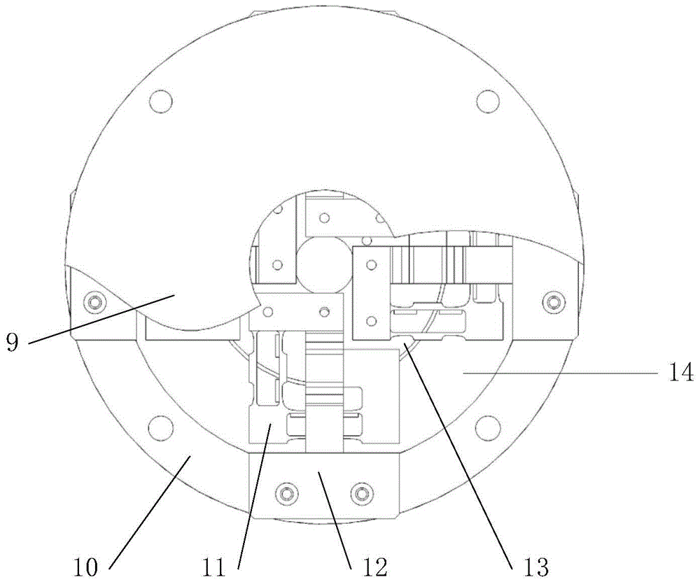
[0028] The present invention provides a wireless measuring device for machine tool cutting force, including an adapter plate 13, a front baffle 14, a mounting base 10, four three-axis force sensors, a back baffle 9 and a wireless module 3; the peripheral equipment is a turning spindle 1 , chuck 4, workpiece 5, milling cutter 6, moving slide 7 and milling spindle 8;

[0029] as attached figure 1 As shown, the adapter plate 13 is a circular rotary part, and its surface is respectively processed with a chuck installation connection hole 27 and a sensor force installation connection hole 25. The central hole on the adapter plate 13 is a chuck The positioning groove 26, the surface on one side of the adapter plate 13 is a force mounting connection plane 28 for the sensor;

[0030] The front baffle 14 is an annular plate-shaped part, and eight mounting holes 22 ...


PUM


Abstract

The invention discloses a wireless measurement device for machine tool cutting force and belongs to the field of mechanical design. The device comprises a turn-connecting plate, a front baffle, an installing base body, a wireless module, four three-axis force sensors and a rear baffle. The four three-axis force sensors and the installing base body are connected into a whole through screws so that the main structure of the wireless measurement device for the cutting force can be formed; the turn-connecting plate is connected with a chuck used for clamping workpieces, and therefore the cutting force can be input; the whole device is sealed through the front baffle and the rear baffle, and the front baffle and the rear baffle play a role of overload protection; after the whole device is fixed to a main shaft, the cutting force of a machine tool can be wirelessly measured through the wireless module. By means of the method, the cutting force borne by the workpieces in the X direction, the Y direction and the Z direction in the precise and fine turning and milling combined machining process can be simultaneously and completely measured at high precision in real time.

Description

technical field [0001] The invention relates to a wireless measuring device for the cutting force of a machine tool in the process of precision micromachining, and belongs to the technical field of mechanical design. Background technique [0002] With the increasing demand for precision micro-systems in various fields such as aviation, aerospace, military, and medical treatment, precision micro-cutting technology has emerged as the times require. The precision micro-machining technology represented by the turn-milling composite processing technology has surpassed the traditional conventional metal cutting processing technology, and has become a supporting technology to make up for the defects of traditional silicon micro-machining methods in the field of non-silicon-based micro-complex structural parts processing. In the process of precision micro-turn-milling composite machining, cutting force is the key factor affecting the processing quality of micro-complex structural pa...

Claims


Application Information

Patent Timeline
Patent Type & Authority Patents(China)
IPC IPC(8): B23Q17/09
CPCB23Q17/0952B23Q2717/00
Inventor 张之敬秦廷海金鑫李钉叶鑫肖木峥
Owner BEIJING INSTITUTE OF TECHNOLOGYGY
Why Eureka
Try Eureka