Axial flow fan

A technology of axial flow and fan, applied in the direction of mechanical equipment, electromechanical devices, non-variable pumps, etc., can solve the problems of reducing product quality, reducing the leakage vortex strength of blade tip, and requiring high precision of winding equipment and tooling, etc. , to achieve the effect of overcoming mechanical friction and load torque, improving the waveform of the air gap magnetic field, and optimizing the distribution of air reluctance

Active Publication Date: 2019-11-08
EMB PAPST VENTILATOR SHANGHAI
View PDF8 Cites 0 Cited by
  • Summary
  • Abstract
  • Description
  • Claims
  • Application Information

AI Technical Summary

Problems solved by technology

[0004] In view of the structure of the above-mentioned axial flow fan, when the motor is used in some special applications, such as the occasion where the starting torque is required and the motor needs to be able to start and respond quickly in a short period of time, the traditional stator with an equal inner diameter cannot better meet the requirements
Although the rotor chute can solve these problems, the rotor chute method will bring special design of fixtures, increase investment and production cycle, affect production efficiency, and the force of the rotor chute is unbalanced (such as image 3 ), will affect the reliability of the product and reduce the quality of the product
In addition, the motor uses the flying fork method for stator winding, which takes a long time to wind, and requires high precision of winding equipment and tooling, and equipment investment is also large
Regarding the impeller, the blades of existing fans (such as Figure 4 ) mainly emphasizes the suppression of the secondary flow from the pressure surface to the suction surface, and reduces the intensity of the leakage vortex at the tip of the blade, and does not control the size of the noise by controlling the direction of the leakage vortex

Method used


Image

  • Axial flow fan
  • Axial flow fan
  • Axial flow fan

Examples


Embodiment Construction

[0036] In order to make the technical problems solved by the present invention, the technical solutions adopted and the technical effects achieved clearer, the technical solutions of the embodiments of the present invention will be further described in detail below in conjunction with the accompanying drawings. Obviously, the described embodiments are only the technical solutions of the present invention. Some, but not all, embodiments. Based on the embodiments of the present invention, all other embodiments obtained by those skilled in the art without creative efforts fall within the protection scope of the present invention.

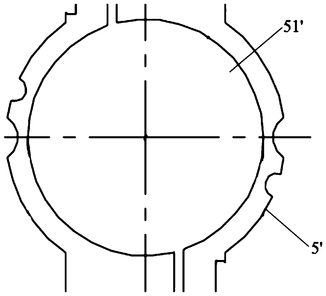
[0037] like Figure 5-Figure 11 As shown, this embodiment provides a preferred axial flow fan, which includes a housing 1, a motor 2, an impeller 3 and blades 4 arranged on the impeller 3, wherein the motor 2 is fixedly installed in the housing 1, The output shaft of the motor 2 is connected with the impeller 3 for driving the impeller 3 and the blade...


PUM


Abstract

The invention discloses an axial flow fan, and relates to the technical field of fans. The axial flow fan comprises a shell, wherein the shell is internally fixedly provided with a motor; an output shaft of the motor is provided with an impeller; the impeller is provided with blades; the motor comprises a stator and a rotor sleeved by the stator; the stator is internally provided with a heteromorphic inner hole with different radii, the heteromorphic inner hole is used for mounting the rotor, and different air clearances are formed between the heteromorphic inner hole and the rotor; the surface of the rotor is provided with V-shaped chutes. By virtue of optimal design of the stator and the rotor, the axial flow fan can be used for overcoming mechanical friction and load torque within a relatively short time, and realizing rapid response; meanwhile, noises and vibration generated in a fan operation process are reduced, additional torque generated by a traditional rotor-chute structure in an axial direction is eliminated, and the overall performance of the axial flow fan is improved.

Description

technical field [0001] The invention relates to the technical field of fans, in particular to an axial flow fan. Background technique [0002] The fan is a machine that relies on the input mechanical energy to increase the gas pressure and discharge the gas. It is a driven fluid machine. Fans are not only widely used in ventilation, dust removal and cooling of factories, mines, tunnels, cooling towers, vehicles, ships and buildings, but also for cooling and ventilation of air conditioning equipment and household appliances. Fans are classified according to the direction of gas flow, and can be divided into centrifugal, axial flow, diagonal flow and cross flow. The research of this application is mainly about the axial flow fan. When the axial flow fan is working, the power machine drives the impeller to rotate in the cylindrical casing, the gas enters from the collector, obtains energy through the impeller, increases the pressure and speed, and then to discharge. [0003]...

Claims


Application Information

Patent Timeline
Patent Type & Authority Patents(China)
IPC IPC(8): F04D25/08F04D29/38F04D29/66H02K1/12H02K1/22H02K3/46
CPCF04D25/0633F04D25/064F04D25/0646F04D25/08F04D29/386F04D29/663F04D29/667H02K1/12H02K1/22H02K3/46H02K2201/03
Inventor 程颐颢宋文杰郑成勇
Owner EMB PAPST VENTILATOR SHANGHAI
Why Eureka
Try Eureka