Refrigeration equipment and heat exchange assembly for same

A technology of refrigeration equipment and heat exchangers, which is applied in household heating, household heating, lighting and heating equipment, etc., and can solve the problems of poor heat exchange effects, large differences in air volume of heat exchangers, and differences in heat exchange effects of heat exchangers Large and other problems, to achieve the effect of improving heat transfer uniformity and heat transfer efficiency

Inactive Publication Date: 2015-07-22
GD MIDEA AIR-CONDITIONING EQUIP CO LTD +1
View PDF5 Cites 5 Cited by
  • Summary
  • Abstract
  • Description
  • Claims
  • Application Information

AI Technical Summary

Problems solved by technology

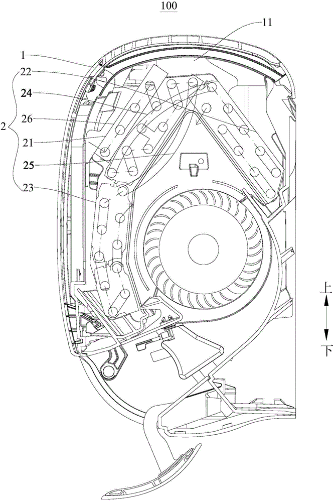
In this way, due to structural limitations and aesthetic requirements, the air volume of each part of the heat exchanger of the refrigeration equipment varies greatly.
At this time, if the flow path is still designed according to the past, it will inevitably cause large differences in the heat transfer effect of each part of the heat exchanger, and the overall heat transfer effect will be poor.

Method used


Image

  • Refrigeration equipment and heat exchange assembly for same
  • Refrigeration equipment and heat exchange assembly for same

Examples


Embodiment Construction

[0030] Embodiments of the present invention are described in detail below, examples of which are shown in the drawings, wherein the same or similar reference numerals designate the same or similar elements or elements having the same or similar functions throughout. The embodiments described below by referring to the figures are exemplary only for explaining the present invention and should not be construed as limiting the present invention.

[0031] In describing the present invention, it should be understood that the terms "center", "longitudinal", "transverse", "length", "width", "thickness", "upper", "lower", "front", " Orientation indicated by rear, left, right, vertical, horizontal, top, bottom, inside, outside, clockwise, counterclockwise, etc. The positional relationship is based on the orientation or positional relationship shown in the drawings, which is only for the convenience of describing the present invention and simplifying the description, rather than indicati...


PUM


Abstract

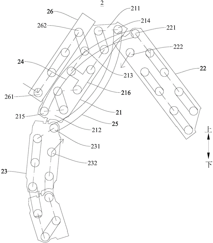
The invention discloses refrigeration equipment and a heat exchange assembly for the refrigeration equipment. The refrigeration equipment comprises a shell and the heat exchange assembly. The heat exchange assembly comprises a flow split heat exchanger, a close-to-ventilation-opening heat exchanger, a away-from-ventilation-opening heat exchanger, a first communication pipe and a second communication pipe, wherein the flow split heat exchanger is provided with a close-to-ventilation-opening portion adjacent to a ventilation opening and a away-from-ventilation-opening portion away from the ventilation opening; the close-to-ventilation-opening heat exchanger is provided with a close-to-ventilation-opening heat exchanger inlet and a close-to-ventilation-opening heat exchanger outlet; the away-from-ventilation-opening heat exchanger is provided with a away-from-ventilation-opening heat exchanger inlet and a away-from-ventilation-opening heat exchanger outlet; the two ends of the first communication pipe are communicated with a away-from-ventilation-opening portion outlet and a close-to-ventilation-opening heat exchanger inlet to lead refrigerants flowing out of the away-from-ventilation-opening portion outlet into the close-to-ventilation-opening heat exchanger; the two ends of the second communication pipe are communicated with a close-to-ventilation-opening portion outlet and the away-from-ventilation-opening heat exchanger inlet to lead refrigerants flowing out of the close-to-ventilation-opening portion outlet into the away-from-ventilation-opening heat exchanger. The heat exchange assembly of the refrigeration equipment is even in heat exchange.

Description

technical field [0001] The invention relates to the refrigeration field, in particular to a refrigeration equipment and a heat exchanger assembly used in the refrigeration equipment. Background technique [0002] With the development of the times, people put forward higher and higher requirements for the aesthetics of products. The fuselage of existing refrigeration equipment is getting thinner and thinner, the air inlet is becoming more and more hidden, or the front grille is denser, and it is not allowed to look directly into the inside of the fuselage. In this way, due to structural limitations and aesthetic requirements, the air volume of each part of the heat exchanger of the refrigeration equipment varies greatly. At this time, if the flow path is still designed according to the past, it will inevitably cause great differences in the heat transfer effect of each part of the heat exchanger, and the overall heat transfer effect will be poor. Contents of the invention ...

Claims


Application Information

Patent Timeline
Patent Type & Authority Applications(China)
IPC IPC(8): F24F1/00F24F13/30
CPCF24F1/00F24F13/30
Inventor 刘燕飞戚文端郭振标
Owner GD MIDEA AIR-CONDITIONING EQUIP CO LTD
Why Eureka
Try Eureka