

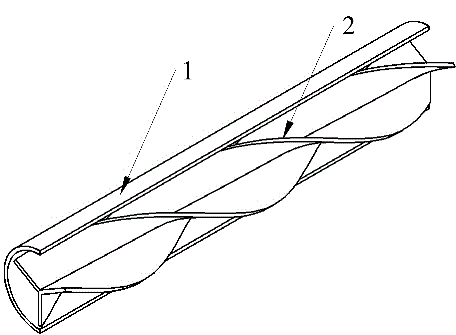
Trilateral spiral twisted band
A technology of helical ties and spirals, applied in the field of new three-sided helical ties, can solve the problems that the comprehensive performance needs to be further improved, the fluid flow resistance is increased, etc., and achieve the effect of strong turbulence effect, increased fluid flow, and sufficient heat exchange.
Inactive Publication Date: 2015-07-22
ZHENGZHOU UNIV
View PDF7 Cites 9 Cited by
- Summary
- Abstract
- Description
- Claims
- Application Information
AI Technical Summary
Problems solved by technology
Compared with ordinary torsion, although the strengthening effect of the special-shaped bond has been improved to a certain ext
Method used
View moreImage
Smart ImageViewing Examples


Examples
 PUM
| Property | Measurement | Unit |
|---|---|---|
| Thickness | aaaaa | aaaaa |
| Angle | aaaaa | aaaaa |
Abstract
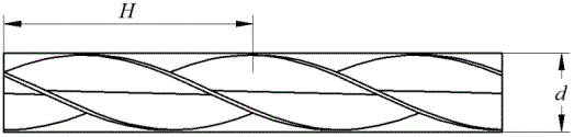
The invention discloses a trilateral spiral twisted band. The trilateral spiral twisted band is characterized in that the trilateral spiral twisted band is of a periodic structure and is formed by three width-equal metal sheets with the thickness of being about 1 mm, long edges of the three metal sheets are welded together in a butt joint mode, and the included angle between every two adjacent metal sheets is 120 degrees; the trilateral spiral twisted band is formed in a spiral twisting and fabricating mode, and the twisting rate of the trilateral spiral twisted band is about 2.0; the outer diameter of the trilateral spiral twisted band is 0.5 mm-1.0 mm smaller than the inner diameter of a heat exchange pipe, and the length of the trilateral spiral twisted band is generally equal to or smaller than that of the heat exchange pipe; the trilateral spiral twisted band is inserted into the heat exchange pipe without a fixing device; materials for the trilateral spiral twisted band are determined according to specific working conditions; as for occasions with corrosive media, stainless steel can be selected for the trilateral spiral twisted band, and the trilateral spiral twisted band can also be formed in a plastic injection moulding mode; as for occasions without corrosive media, plain carbon steel is selected for the trilateral spiral twisted band. The trilateral spiral twisted band is simple in structure and convenient to install, can be directly inserted into the heat exchange pipe, has dual functions of strengthening of heat transfer of fluid in the pipe and scale prevention, and is good in economical efficiency and high in practicability.
Description
technical field [0001] The patent of the present invention relates to an insert in a pipe, that is, a tie, in particular to a new type of trilateral spiral tie used in a heat exchange pipe to enhance fluid heat exchange and prevent fouling. Background technique [0002] Heat exchange equipment is widely used in petroleum, chemical, power, nuclear energy, metallurgy, refrigeration and other industries, and is a basic equipment for heat transfer. For example, in an oil refinery, heat exchange equipment accounts for about 35% to 40% of all process equipment investment, and the efficiency of heat exchange equipment is of great significance to energy saving. It is an important topic in the current research field of heat exchangers to adopt enhanced heat transfer technology and improve the efficiency of heat exchangers. [0003] Among the many enhanced heat transfer measures, the advantages of using in-tube enhanced heat transfer elements such as coil springs, helical sheets, rot...
Claims
Login to View More Application Information
Patent Timeline
 IPC IPC(8): F28F13/12
Inventor吴金星王超刘艳会王明强李亚飞彭旭栗俊芬
OwnerZHENGZHOU UNIV