
Revolution speed adapter plate for turbine

A technology of steam turbines and adapter plates, which is applied in the direction of devices using electric/magnetic methods, can solve the problems of difficulty in balancing accuracy and reliability, and achieve the effect of avoiding inaccurate low-speed measurement

Active Publication Date: 2015-07-22
HARBIN TURBINE
View PDF3 Cites 1 Cited by
  • Summary
  • Abstract
  • Description
  • Claims
  • Application Information

AI Technical Summary

Problems solved by technology

[0003] The purpose of the present invention is to solve the problem that the existing speed measurement sensors of steam turbines are limited by their respective functions, making it difficult to balance accuracy and reliability, and provide a speed adapter plate for steam turbines

Method used


Image

  • Revolution speed adapter plate for turbine
  • Revolution speed adapter plate for turbine

Examples


specific Embodiment approach 1

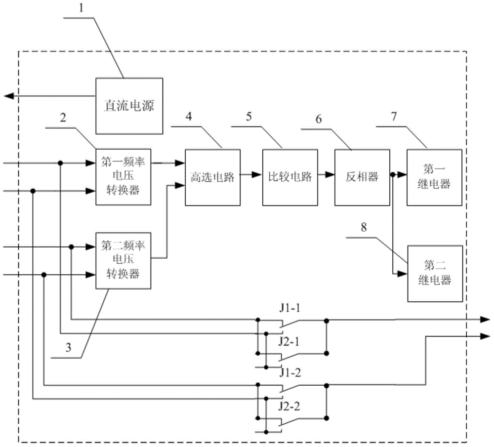
[0019] Specific implementation mode one: the following combination figure 1 and figure 2 Describe this embodiment, the steam turbine speed adapter board described in this embodiment includes a DC power supply 1, a first frequency-to-voltage converter 2, a second frequency-to-voltage converter 3, a high-selection circuit 4, a comparison circuit 5, and an inverter 6. The first relay 7 and the second relay 8,

[0020] DC power supply 1 is used to provide working power for the eddy current speed sensor;

[0021] The positive input end of the first frequency voltage converter 2 is connected to the pulse signal positive output end of the eddy current speed sensor, and the negative input end of the first frequency voltage converter 2 is connected to the pulse signal negative output end of the eddy current speed sensor;

[0022] The positive input end of the second frequency voltage converter 3 is connected to the positive output end of the unequal amplitude sine wave signal of the...

specific Embodiment approach 2

[0032] Specific implementation mode two: the following combination figure 2 This embodiment will be described. This embodiment will further describe the first embodiment. The voltage threshold set by the comparator circuit 5 is the corresponding voltage value when the steam turbine speed is 500 RPM.

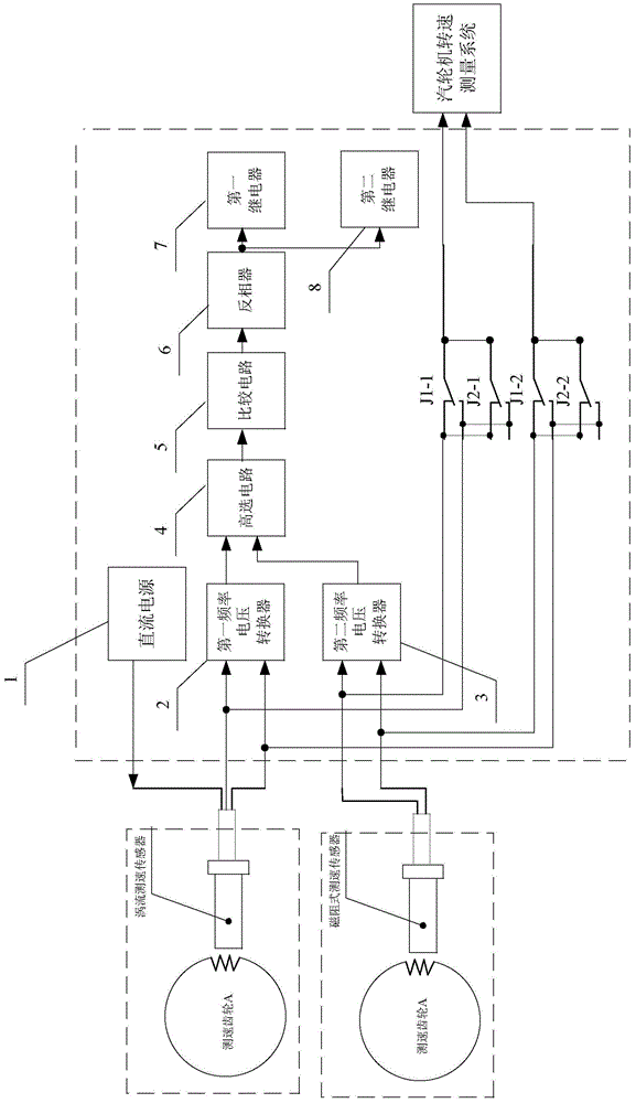
[0033] When the rotation speed is greater than 500 rpm, the two relays are controlled to lose power, the normally open contacts of the relays are disconnected, and the normally closed contacts are closed. When it is equal to 500 revolutions, the pulse signal of the eddy current speed sensor is output.

[0034] figure 2 As shown, the steam turbine eddy current speed sensor enters the first channel of the adapter board, the DC power supply of the eddy current speed sensor is provided by the steam turbine speed adapter board, and the steam turbine reluctance speed sensor enters the second channel of the adapter board, and the steam turbine speed is low When the speed is at or eq...


PUM


Abstract

The invention relates to a revolution speed adapter plate for a turbine, which belongs to the technical field of turbine revolution speed measurement. The revolution speed adapter plate for the turbine aims at solving the problem that as the revolution speed measuring transducers of existing turbines are limited by respective functions, giving consideration to both accuracy and reliability is very difficult. The revolution speed adapter plate for the turbine comprises a direct-current power supply, a first frequency voltage converter, a second frequency voltage converter, a high selective circuit, a comparison circuit, an inverter, a first relay and a second relay, the two frequency voltage converters respectively receive speed signals output by a magnetic resistance type speed measuring transducer and an eddy speed measuring transducer, a greater value is output by the high selective circuit, after the greater value is compared with the voltage threshold value of the comparison circuit, an inverter is adopted to control the relay to gain power or lose power according to the level signal of the comparison circuit, and a revolution speed signal is selected to be output. The revolution speed adapter plate for the turbine is used for selecting and outputting the revolution speed signal obtained by the speed measuring transducer.

Description

technical field [0001] The invention relates to a speed adapter plate of a steam turbine and belongs to the technical field of speed measurement of a steam turbine. Background technique [0002] At present, there are two ways to measure the speed of the steam turbine. One way is to use a magnetoresistive speed sensor. Its advantages are that it does not need an external power supply, the sensor has a simple structure, is easy to install and use, and has high reliability. The disadvantage is that the sine wave induced at low speed The wave amplitude is small and susceptible to interference, resulting in inaccurate or impossible measurement of the turbine speed; another way is to use an eddy current speed sensor, which has the advantage of being able to output standard speed pulses within the effective range of the speed of the steam turbine from 0 to 3600RPM The signal, measurement and display unit can accurately measure the speed of the steam turbine. The disadvantage is tha...

Claims


Application Information

Patent Timeline
Patent Type & Authority Applications(China)
IPC IPC(8): G01P3/49
Inventor 王春月林守玉周明钢胡宁伊静
Owner HARBIN TURBINE
Learn More