Method and device for compensating spherical aberration of particle velocity imager

A technology of particle velocity and spherical aberration, which is applied in the direction of particle separation tubes, instrument calibration, and parts of particle separator tubes, etc. It can solve the problems of low improvement in device resolution, influence of velocity image resolution, high complexity, etc. problems, to achieve the effect of simple implementation, low cost, and prevention of under-compensation or over-compensation

Inactive Publication Date: 2017-10-31
HUAZHONG UNIV OF SCI & TECH
View PDF3 Cites 0 Cited by
  • Summary
  • Abstract
  • Description
  • Claims
  • Application Information

AI Technical Summary

Problems solved by technology

This has a large impact on the resolution of the velocity images
[0004] In the prior art, the resolution of the device is usually increased by adding multiple electrode plates, grids, etc. This method is complex and costly, and the degree of improvement in the resolution of the device is not high

Method used


Image

  • Method and device for compensating spherical aberration of particle velocity imager
  • Method and device for compensating spherical aberration of particle velocity imager
  • Method and device for compensating spherical aberration of particle velocity imager

Examples


Embodiment Construction

[0019] In order to make the object, technical solution and advantages of the present invention clearer, the present invention will be further described in detail below in conjunction with the accompanying drawings and embodiments. It should be understood that the specific embodiments described here are only used to explain the present invention, not to limit the present invention. In addition, the technical features involved in the various embodiments of the present invention described below can be combined with each other as long as they do not constitute a conflict with each other.

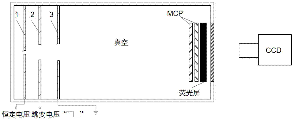
[0020] The device of the invention adds a jump voltage to the extraction electrode plate of the existing particle velocity imager to realize the effect of adding a divergent electric field on the basis of the focusing electric field, thereby achieving the purpose of compensating the spherical aberration of the original electrostatic focusing lens. figure 1 It is a schematic structural diagram of...


PUM


Abstract

The invention discloses a method for compensating for spherical aberration of a particle speed projector. The method includes the step of adding a leaping voltage to an extracting pole plate electrode of the particle speed projector so that a divergence electric field can be added on the basis of a focusing electric field and the spherical aberration of an existing electrostatic focusing lens can be compensated for. The invention further provides a device for compensating for the spherical aberration of the particle speed projector. The device comprises a leaping voltage control unit connected with the extracting pole plate electrode of the particle speed projector and used for generating the leaping voltage on the extracting pole plate electrode. The existing electrostatic focusing lens spherical aberration of the particle speed projector can be compensated for, the existing device structure does not need to be changed when the method is implemented, implementation is easy and convenient, cost is low, and the image resolution ratio is high.

Description

technical field [0001] The invention relates to the technical field of particle velocity imaging, and more specifically, to a method and device for compensating spherical aberration of a particle velocity imaging instrument. Background technique [0002] The particle velocity imaging technology developed in the late 1980s has been playing an important role in the understanding of photodissociation / ionization reactions. The core components of the particle velocity imager are three circular electrode plates with a hole in the middle, which are the repeller electrode plate, the extractor electrode plate and the ground electrode plate. The electric field formed by these three electrode plates constitutes the electrostatic lens. Ions / electrons generated at different positions and with the same momentum are repelled by the repeller electrode plate, focused by the extractor electrode plate and the ground electrode plate, and converged on the microchannel plate (MCP) detector. Fin...

Claims


Application Information

Patent Timeline
Patent Type & Authority Patents(China)
IPC IPC(8): H01J49/00
CPCH01J49/0009H01J49/025
Inventor 兰鹏飞陆培祥张鹏张庆斌罗四强
Owner HUAZHONG UNIV OF SCI & TECH
Why Eureka
Try Eureka