Flow field structure of AC excited variable speed generator

A technology of AC excitation and generator, applied in the direction of electrical components, electromechanical devices, electric components, etc., can solve the problems of generator output current, power oscillation, unstable operation, etc., achieve reduced ventilation loss, reasonable distribution, and increased effective height Effect

Inactive Publication Date: 2015-07-22
HARBIN ELECTRIC MASCH CO LTD
View PDF5 Cites 0 Cited by
  • Summary
  • Abstract
  • Description
  • Claims
  • Application Information

AI Technical Summary

Problems solved by technology

When the load of the generator or the input of the prime mover suddenly causes the generator speed to change, it will inevitably cause the swing of the generator power angle, cause the output current and power of the generator to oscillate, and even cause the operation to be unstable. The AC excitation variable speed power generation technology is adopted It is an ideal way to solve the above problems

Method used


Image

  • Flow field structure of AC excited variable speed generator

Examples


Embodiment Construction

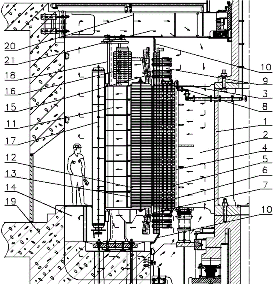
[0012] Such as figure 1 As shown, the flow field structure of an AC excitation variable speed generator consists of a rotor center body 1, a rotor bracket 2, a bracket enclosure 3, a bracket L rib 4, a rotor core 5, a rotor ventilation ditch 6, a rotor coil 7, and a rotor core Pressure plate 8, rotor end coil support 9, windshield 10, stator base 11, stator core 12, stator ventilation ditch 13, lower air duct 14, stator coil 15, collector ring 16, cooler 17, vertical rib ring plate 18. The foundation 19, the upper frame 20 and the upper air duct 21, wherein the rotor bracket 2 is welded on the rotor center body 1, the bracket shroud 3 is welded on the axial side surface of the rotor bracket 2, and the bracket L rib 4 is welded on the rotor On the outer surface of the bracket 2, the rotor core 5 and the rotor ventilation ditch 6 are arranged alternately in the axial direction, and the inner circle is provided with dovetail grooves. The rotor core 5, the rotor ventilation ditch ...


PUM


Abstract

The invention relates to a flow field structure of an AC excited variable speed generator. When flowing by flow areas, cooling air exchanges heat with heating parts, such as a rotor core, a stator coil and a collector ring, thereby dissipating loss heat of the heating parts and ensuring that the temperature of each heating part is in the safety range. Ventilating ducts of a rotor are in ventilating channel steel structures the same as those of stator ventilating ducts; the pressure head action generated by high-speed rotation of a rotor end coil is made full use, and total air flow is increased; in order to avoid large vortexes forming near the rotor end coil, an air baffle is designed; a vertical rib ring plate is provided with air outlets, the problem of stress concentration is solved, effective height of a cooler is increased, cooling water is enabled to bring away more loss heat, the temperature of the cooling air is decreased, and motor cooling is better facilitated. Model tests show that the flow field structure fully meets the cooling needs of variable speed generators.

Description

technical field [0001] The invention relates to a flow field structure of an AC excitation variable speed generator. Background technique [0002] Conventional generators can only run at rated synchronous speed, the unit speed is fixed, and the generator must run at a constant speed under any conditions. When the load of the generator or the input of the prime mover suddenly causes the generator speed to change, it will inevitably cause the swing of the generator power angle, cause the output current and power of the generator to oscillate, and even cause the operation to be unstable. The AC excitation variable speed power generation technology is adopted. It is an ideal way to solve the above problems. [0003] Due to the incomparable advantages and broad application prospects of variable speed generators, many countries, such as the former Soviet Union, Japan and Germany, have conducted extensive research on AC excitation variable speed generators, and gradually used them...

Claims


Application Information

Patent Timeline
Patent Type & Authority Applications(China)
IPC IPC(8): H02K9/10
CPCH02K9/10
Inventor 于涛安志华马文豪刘昱光秦光宇邢广刘双杨越韩荣娜刘维维张浩洋李明宇范吉松丁大鹏
Owner HARBIN ELECTRIC MASCH CO LTD
Why Eureka
Try Eureka