LC voltage-controlled oscillator with automatic output oscillation amplitude correction function

A voltage-controlled oscillator and automatic correction technology, applied in the direction of automatic power control, electrical components, etc., can solve the problems of affecting the quality of the output signal of the oscillator, unable to optimize the phase noise performance, and deteriorating the phase noise of the oscillator.

Inactive Publication Date: 2015-07-22
XIDIAN UNIV
View PDF3 Cites 12 Cited by
  • Summary
  • Abstract
  • Description
  • Claims
  • Application Information

AI Technical Summary

Problems solved by technology

Due to the influence of temperature drift, voltage and manufacturing process, the technology used in the former has a large deviation between the actual output swing and the ideal value, and the output swing cannot be adjusted, which eventually leads to the extremely poor and incapable voltage controlled oscillator. Optimized phase noise performance; although the latter uses a current source array for dynamic output swing adjustment, the noise generated by the tail current source array will pass through the cross-coupled transistor and the inductor-capacitor resonant network in the voltage-controlled oscillator, and the oscillation The signal enters the output signal together, which seriously deteriorates the phase noise of the oscillator; at the same time, the swing detection point is selected at the position of the output signal, so that the noise in the detection circuit also enters the output signal, which seriously affects the quality of the oscillator output signal

Method used


Image

  • LC voltage-controlled oscillator with automatic output oscillation amplitude correction function
  • LC voltage-controlled oscillator with automatic output oscillation amplitude correction function
  • LC voltage-controlled oscillator with automatic output oscillation amplitude correction function

Examples


Embodiment Construction

[0013] In order to make the objects and advantages of the present invention clearer, the present invention will be specifically described below in conjunction with examples. It should be understood that the following words are only used to describe one or several specific implementation modes of the present invention, and do not strictly limit the protection scope of the specific claims of the present invention.

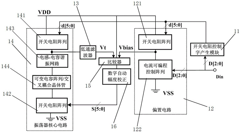
[0014] The technical scheme that the present invention takes is as figure 1 As shown, an output swing automatic correction LC voltage-controlled oscillator includes an oscillator core circuit module 14, a low-pass filter 13, a comparator 15, a digital automatic amplitude correction module 16, a bias circuit module 12 and a switch resistance control The word generation module 11; the oscillator core circuit module 14 is made up of the first switch resistance array 141, the LC resonant network 143, the variable capacitor array / cross-coupled transistor 144 and the secon...


PUM


Abstract

The invention relates to an LC voltage-controlled oscillator with an automatic output oscillation amplitude correction function. The LC voltage-controlled oscillator comprises an oscillator core circuit module, a low-pass filtering device, a comparator, a digital automatic amplitude correction module, a biasing circuit module and a switch resistor control word generation module. The oscillator core circuit module comprises a first switch resistor array, an LC resonance network, a variable capacitor array / cross coupling transistor and a second switch resistor array. The biasing circuit module comprises a third switch resistor array and a current programmable control array. The LC voltage-controlled oscillator has the advantages that the switch resistor arrays are substituted for conventional current source arrays, so that influence of noise in circuits on phase noise of the oscillator is reduced; a biasing circuit is used for adjusting the output oscillation amplitude of the oscillator in real time, and an output amplitude detection loop is formed by the low-pass filtering device, the comparator and the digital automatic amplitude correction module; output signal amplitude detection points are selected between a resonance network and the switch resistor arrays, and accordingly, influence of detection loop noise on oscillator output signals is reduced.

Description

technical field [0001] The invention relates to the field of oscillators, in particular to an LC voltage-controlled oscillator with automatic output swing correction. Background technique [0002] The output swing of the previous voltage-controlled oscillator is controlled at a specific value through circuit design, or the tail current source array is used to dynamically adjust the output swing. Due to the influence of temperature drift, voltage and manufacturing process, the technology used in the former has a large deviation between the actual output swing and the ideal value, and the output swing cannot be adjusted, which eventually leads to the extremely poor and inability of the voltage controlled oscillator. Optimized phase noise performance; although the latter uses a current source array for dynamic output swing adjustment, the noise generated by the tail current source array will pass through the cross-coupled transistor and the inductor-capacitor resonant network i...

Claims


Application Information

Patent Timeline
Patent Type & Authority Applications(China)
IPC IPC(8): H03L7/099
Inventor 李迪杨银堂李跃进石佐辰
Owner XIDIAN UNIV
Why Eureka
Try Eureka