Brake fluid pressure control apparatus

A technology of brake hydraulic pressure and control device, which is applied in the directions of brakes, brake components, control valves and air release valves, etc., can solve the problems of reducing the size of the brake hydraulic control device and increasing the width and size, and achieves the reduction of assembly space, The effect of reducing leakage and preventing corrosion

Active Publication Date: 2015-07-22
ADVICS CO LTD
View PDF8 Cites 4 Cited by
  • Summary
  • Abstract
  • Description
  • Claims
  • Application Information

AI Technical Summary

Problems solved by technology

[0007] Therefore, the width dimension of the housing that incorporates the piston pump and the solenoid valve for increasing / decreasing increases, and there is a limit to reducing the size of the brake hydraulic pressure control device.

Method used


Image

  • Brake fluid pressure control apparatus
  • Brake fluid pressure control apparatus
  • Brake fluid pressure control apparatus

Examples


Embodiment Construction

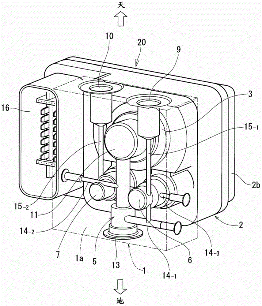
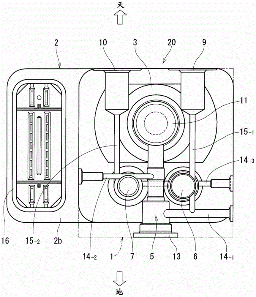
[0032] Below, based on the drawings in the description Figure 1 to Figure 7 Embodiments of the brake fluid pressure control device of the present invention will be described.

[0033] Figure 7 It is a circuit diagram of an example of a hydraulic brake device using the brake hydraulic pressure control device of the present invention. This hydraulic brake device 30 is used for two-wheel vehicles, including: the master cylinder 33 of the first system, which works through one brake lever 31; the master cylinder 34 of the second system, which works through the brake lever 32 of the other side operation; the wheel cylinder 35 of the first system and the wheel cylinder 36 of the second system; and the brake hydraulic pressure control device 20 provided in the hydraulic pressure path from the master cylinder 33 of the first system to the wheel cylinder 35 of the system.

[0034] The first system and the second system are independent systems, and the hydraulic pressure of the wheel...


PUM


Abstract

The purpose is to decrease the physical size of a brake fluid pressure control apparatus for implementing pressure increasing / decreasing control for the fluid pressure in a wheel cylinder. A brake fluid pressure control apparatus is provided with: a piston pump (5); a pump drive motor (3); an eccentric cam rotated by the motor to activate the piston pump; a pressure-increasing electromagnetic valve (6); and a pressure-decreasing electromagnetic valve (7), in which the piston pump (5), the eccentric cam, the pressure-increasing electromagnetic valve (6), and the pressure-decreasing electromagnetic valve (7) are assembled in a housing (1a). The single piston pump (5) is installed, with the piston pump (5), when mounted on a vehicle, disposed in an upright posture under or above a cam chamber (11) of the housing in which the eccentric cam is housed.

Description

technical field [0001] The present invention relates to a brake fluid pressure control device including a motor-driven pump used in a hydraulic brake system of a vehicle. Background technique [0002] The brake fluid pressure control device for vehicles is arranged on the hydraulic pressure path from the master cylinder to the wheel cylinders, and controls the increase and decrease of the wheel cylinder hydraulic pressure for the purpose of avoiding wheel lock, etc. There is an example, for example, what is disclosed in the following patent document 1. [0003] The brake hydraulic pressure control device disclosed in this document is provided with an eccentric cam and a piston pump, and the piston pump operates by using a motor that rotates the eccentric cam as a power source and driven by the power source. There are two sets of the piston pumps, and the two sets of piston pumps are respectively arranged in the front wheel system and the rear wheel system of the two-wheeled...

Claims


Application Information

Patent Timeline
Patent Type & Authority Applications(China)
IPC IPC(8): B60T8/34
CPCB60T8/368B60T8/3225
Inventor 关原康仁大岛裕贵
Owner ADVICS CO LTD
Why Eureka
Try Eureka