Transceiver front-end

A transceiver front-end and receiver technology, applied in electrical components, transmission systems, etc., can solve the problems of complexity, loss of power of received signals and transmitted signals, and implementation sensitivity.

Inactive Publication Date: 2015-07-22
TELEFON AB LM ERICSSON (PUBL)
View PDF1 Cites 4 Cited by
  • Summary
  • Abstract
  • Description
  • Claims
  • Application Information

AI Technical Summary

Problems solved by technology

Therefore, the implementation is sensitive and complex
Other disadvantages of this solution are that due to the matching impedance of

Method used


Image

  • Transceiver front-end
  • Transceiver front-end
  • Transceiver front-end

Examples


Embodiment Construction

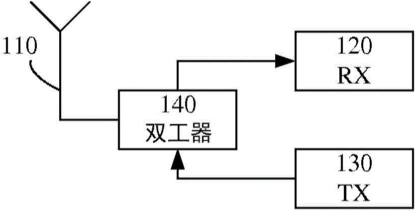
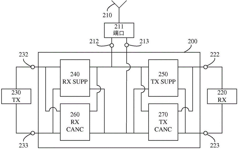
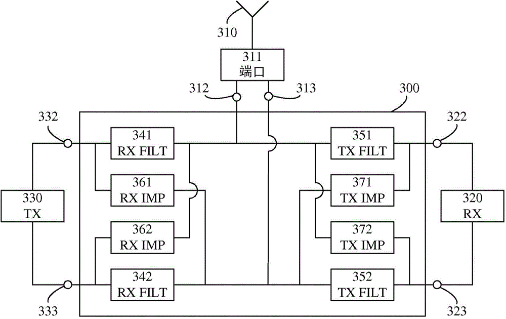
[0079] In the following, an embodiment will be described in which a transceiver structure including a receiver, a transmitter, a signal transmitting and receiving device (eg, an antenna), and a transceiver front end is provided. The transceiver front end of an embodiment may be connected to signal transmission and reception devices, transmitters and receivers. Each of the respective connection interfaces may eg be single-ended (comprising one connection node) or differential (comprising two connection nodes).

[0080] The transmitter is adapted to generate a transmission signal having a transmission frequency. A transmitted signal is intended to be transmitted by a signal transmitting and receiving device. The receiver is adapted to process received signals received by the signal transmitting and receiving means and having a received frequency. Even though a signal is transmitted to a signal transmitting and receiving device, a part of the transmitted frequency may leak to t...


PUM


Abstract

A transceiver front-end for a communication device is connectable to a signal transmission and reception arrangement (310) adapted to transmit a transmit signal having a transmit frequency and to receive a receive signal having a receive frequency. The transceiver front-end is also connectable to a transmitter (330) adapted to produce the transmit signal, and to a receiver (320) adapted to process the receive signal. The transceiver front-end comprises a transmit frequency suppression filter arrangement (351, 352) and a receive frequency suppression filter arrangement (341, 342). The transmit frequency suppression filter arrangement is adapted to suppress transfer of a signal having the transmit frequency and to pass a signal having the receive frequency. The receive frequency suppression filter arrangement is adapted to suppress transfer of a signal having the receive frequency and to pass a signal having the transmit frequency. The transceiver front-end also comprises a transmit frequency cancellation arrangement (371, 372) and a receive frequency cancellation arrangement (361, 362). The transmit frequency cancellation arrangement is adapted to produce a first cancellation signal for cancellation, at receiver nodes (322, 323), of a suppressed signal having the transmit frequency, transferred by the transmit frequency suppression filter arrangement. The receive frequency cancellation arrangement is adapted to produce a second cancellation signal for cancellation, at signal transmission and reception arrangement nodes (312, 313), of a suppressed signal having the receive frequency, transferred by the receive frequency suppression filter arrangement. Corresponding transceiver, communication device and method are also disclosed.

Description

technical field [0001] The present invention relates generally to the field of transceiver front ends for communication devices. More specifically, the present invention relates to transceiver front ends that provide isolation between a transmitter and a receiver. Background technique [0002] In a transceiver for frequency division duplex (FDD) communication, such as that of a cellular radio, the receiver typically experiences strong interfering signals from the transmitter of the same transceiver. [0003] The interfering signal from the transmitter has a carrier frequency at a duplex distance from the carrier frequency of the received signal. Typical duplex distances are small compared to the carrier frequency. Typically, the duplex distance may be less than 100 MHz, while the carrier frequency may be, for example, somewhere between 700 MHz and 3 GHz. [0004] In order to be able to operate with the desired performance (e.g., to achieve good sensitivity), the receiver ...

Claims


Application Information

Patent Timeline
IPC IPC(8): H04B1/525
CPCH04B1/525H04B1/48H04B2001/485
Inventor 亨利克·斯约兰达斯蒂芬·安德森伊马德丁约翰·韦内哈格
Owner TELEFON AB LM ERICSSON (PUBL)
Why Eureka
Try Eureka