Adjustable pneumatic miller fixture

A milling machine fixture and adjustable technology, applied in the direction of clamping, manufacturing tools, supports, etc., can solve problems such as affecting work efficiency and large difference in workpiece height, and achieve the effect of flexible use and increased use range

Inactive Publication Date: 2015-07-29
SUZHOU HUALAI PHOTOELECTRIC INSTR
View PDF6 Cites 2 Cited by
  • Summary
  • Abstract
  • Description
  • Claims
  • Application Information

AI Technical Summary

Problems solved by technology

[0003] The traditional pneumatic milling machine fixture, because the moving range of the top plate is relatively small, and the height difference of the workpiece to be processed is relatively large, so when processing products with different heights, different fixtures need to be replaced, which affects the work efficiency

Method used


Image

  • Adjustable pneumatic miller fixture

Examples


Embodiment Construction

[0014] The technical solutions of the present invention will be further described in detail below in conjunction with the accompanying drawings and specific embodiments, so that those skilled in the art can better understand and implement the present invention, but the examples cited are not intended to limit the present invention.

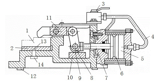
[0015] An adjustable pneumatic milling machine fixture, such as figure 1 As shown, it includes an air valve 3 arranged on the clamp body. The air valve 3 is connected to a cylinder 5 through a connecting pipe 4. The cylinder 5 is the power device of the clamp. The cylinder 5 is provided with a piston 6 and a piston rod. The end of 7 is connected to a single hinge lever 9 through a roller 8, and the other end of the lever 9 is connected to a top pressure plate 11 for pressing the surface of the workpiece 1. The lever 9 changes the horizontal force into a vertical clamping force.

[0016] Preferably, a clamping portion is provided on the inner side of t...


PUM


Abstract

The invention discloses an adjustable pneumatic miller fixture. The adjustable pneumatic miller fixture is characterized by comprising an air distribution valve arranged on a fixture body, wherein the air distribution valve is connected with an air cylinder through a communicating pipe; a piston is arranged inside the air cylinder; the tail end of the piston rod is connected with a single-hinge lever through a roller; the other end of the lever is connected with a propping plate for compacting a surface of workpiece; a support block is arranged between the bottom of the roller and the fixture body; a support plate is arranged between the workpiece and the fixture body; a plurality of blind holes are formed in the bottom of the support plate and fixedly arranged on the fixture body through a plurality of screws. Preferably, a positioning key is arranged on the fixture body; the fixture body is connected with a T-shaped groove on a miller workbench through the positioning key. Clamping of workpieces at different heights is facilitated; impact of processing efficiency caused by replacement of the fixture is avoided and usage scope of the fixture is increased.

Description

Technical field [0001] The invention relates to an adjustable pneumatic milling machine clamp. Background technique [0002] In the machining process, the workpiece will be subjected to cutting force, centrifugal force, inertial force and gravity, etc., in order to ensure that under these external forces, the workpiece can still be processed in the fixture by the positioning element to determine the processing position, without vibration and displacement Therefore, a certain clamping device must be provided in the fixture structure to reliably clamp the workpiece. [0003] Traditional pneumatic milling machine fixtures have a relatively small moving range of the top pressure plate and a large gap in the height of the workpiece to be processed. Therefore, when processing products of different heights, different fixtures need to be replaced, which affects work efficiency. Summary of the invention [0004] In view of the above-mentioned problems, the present invention provides an adju...

Claims


Application Information

Patent Timeline
Patent Type & Authority Applications(China)
IPC IPC(8): B23Q3/08
CPCB23Q3/08B23Q3/103
Inventor 薛文英
Owner SUZHOU HUALAI PHOTOELECTRIC INSTR
Why Eureka
Try Eureka