
A centrifugal compressor or air blower for high speed motor

A technology of centrifugal compressors and high-speed motors, applied in the direction of machines/engines, mechanical equipment, liquid fuel engines, etc., can solve the problems of high energy consumption and achieve the effect of reducing friction loss

Inactive Publication Date: 2015-07-29
SHANGHAI UNITED COMPRESSOR
View PDF6 Cites 6 Cited by
  • Summary
  • Abstract
  • Description
  • Claims
  • Application Information

AI Technical Summary

Problems solved by technology

[0004] In view of the above problems, the present invention provides a centrifugal compressor or blower for high-speed motors to solve the problem of excessive energy consumption caused by traditional cooling methods

Method used


Image

  • A centrifugal compressor or air blower for high speed motor
  • A centrifugal compressor or air blower for high speed motor
  • A centrifugal compressor or air blower for high speed motor

Examples


Embodiment 1

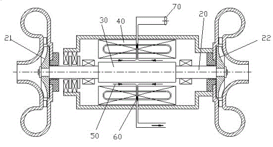
[0020] see figure 2 , the two ends of the rotor shaft 20 are respectively provided with the impeller 21 and the impeller 22, and the middle position is the motor rotor 30.

[0021] The air shown at 50 is inhaled from the atmosphere, from both ends of the motor rotor 30, the negative pressure cooling air 60 passes through the stator 40 through the middle position, is discharged through the vacuum pump 70 or the air injector, and released into the atmosphere. figure 2 As shown, the lower exhaust channel communicates with the upper exhaust channel and shares a vacuum pump 70 .

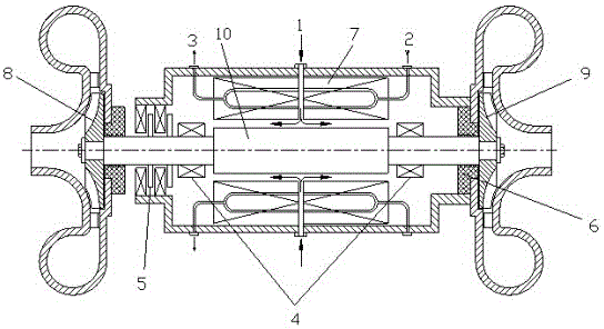
[0022] and figure 1 Compared with the cooling air pressure is low, the air friction loss is less, which can improve the overall efficiency.

Embodiment 2

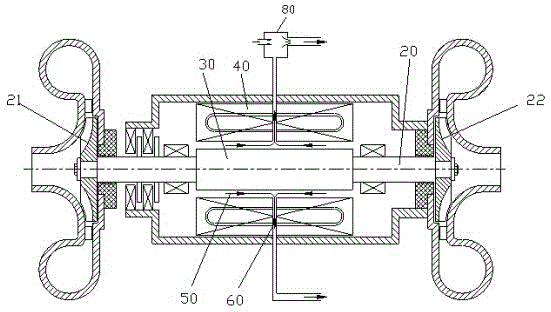
[0024] see image 3 ,and figure 2 The difference is that the air is exhausted by the air jet vacuum pump 80 and released into the atmosphere. image 3 In the figure shown, the lower exhaust channel communicates with the upper exhaust channel and shares a common space. Gas injector 80.

[0025] see Figure 4 , a blower for a high-speed motor, the impeller 21 is directly connected to the high-speed motor 23, the air shown at 50 is sucked from the atmosphere, sucked from both ends of the motor rotor 30, the negative pressure cooling air 60 passes through the stator 40 through the middle position, and passes through the vacuum pump or Air ejector exhaust, release to atmosphere.


PUM


Abstract

The circumferential speed of a traditional centrifugal compressor or an air blower for a high speed motor is high, frictional loss between the surface of a rotor and air is high, so as to cause the rotor to generate heat, and the rotor is always cooled by a large amount of compressed air. By such a way, the consumption rate is high, and the overall efficiency of equipment is reduced. The invention discloses a centrifugal compressor or an air blower for the high speed motor, the surface of the rotor is positioned under a negative pressure environment, so as to use a negative pressure air cooling method to cool instead of cooling by the comprised air, and the efficiency is improved by reducing the frictional loss. Equipment such as vacuum pump or an air ejector is needed for making the negative pressure environment. The main aim of the centrifugal compressor or the air blower for the high speed motor is to reduce the loss caused by the traditional method that cooling air is used for cooling the rotor.

Description

technical field [0001] The invention relates to a centrifugal compressor or blower for a high-speed motor, the rotating speed of the rotor is above 10000rpm. In the compressor used as the gas source for production, the invention minimizes the number of parts. Among them, instead of using traditional gears to increase the speed of the centrifugal compressor, it is directly driven by a high-speed motor. Since the turbine spins at a low speed, the centrifugal compressor cannot work adequately, so the turbine has to spin at high speed. Traditional machines have always used gear speed increasers. Background technique [0002] Recently, high-speed motors have been developed, so it is possible to directly use high-speed motors for driving without considering the use of gears. The traditional rotor cooling method is to use a large amount of compressed air for cooling, and the excessive energy consumption has become a major problem. [0003] figure 1 Is a schematic diagram of the...

Claims


Application Information

Patent Timeline
IPC IPC(8): F04D25/08
CPCF04D25/064F04D29/5806F04D29/582
Inventor 长谷川和三
Owner SHANGHAI UNITED COMPRESSOR
Learn More