Waste heat recovery dryer of high temperature heat pump

A high-temperature heat pump and waste heat recovery technology, applied in dryers, drying, drying gas layout, etc., can solve the problems of long baking time, waste of thermal energy resources, trouble and so on

Inactive Publication Date: 2015-07-29
HUBEI KEYANG ENERGY SAVING EQUIP
View PDF5 Cites 7 Cited by
  • Summary
  • Abstract
  • Description
  • Claims
  • Application Information

AI Technical Summary

Problems solved by technology

[0002] The traditional dryer and barn are designed separately, which not only causes complicated and troublesome installation, high equipment production costs, waste heat is directly discharged to the outside, and the recover

Method used


Image

  • Waste heat recovery dryer of high temperature heat pump

Examples


Embodiment Construction

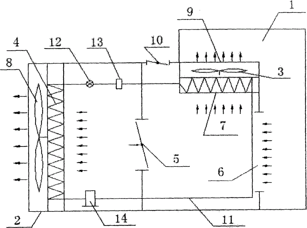
[0012] In this example, refer to figure 1 As shown, a high-temperature heat pump waste heat recovery dryer includes a barn 1 and a high-temperature heat pump 2 connected to the barn 1; 3 The evaporator 4 on the right side, and the first electric regulating valve 5 arranged on the right side of the evaporator 4, and the return air outlet 6 arranged on the right end of the high temperature heat pump 2 and communicated with the barn 1, and arranged in the high temperature heat pump 2 The condenser 7 in the upper right corner, the second fan 8 arranged on the condenser 7, the air outlet 9 arranged on the second fan 8, and the second electric regulating valve 10 arranged on the left side of the air outlet 9.

[0013] Wherein, a pipeline 11 is provided between the evaporator 4 and the condenser 7 to connect, and the connection between the evaporator 4, the condenser 7 and the pipeline 11 is arranged in a rectangular shape: the pipeline 11 is also provided with a joint Flow device 1...


PUM


Abstract

The invention discloses a waste heat recovery dryer of a high temperature heat pump. The waste heat recovery dryer comprises a curing barn and a high temperature heat pump connected with the curing barn; the waste heat recovery dryer further comprises a first fan, an evaporator, a first electric adjusting valve, an air return port, a condenser, a second fan, an air delivery port and a second electric adjusting valve, wherein the first fan is arranged in the left end of the high temperature heat pump, the evaporator is arranged at the right side of the first fan, and the first electric adjusting valve is arranged at the right side of the evaporator; the air return port is formed in the right end of the high temperature heat pump and is communicated with the curing barn, the condenser is arranged at the right upper corner in the high temperature heat pump, the air delivery port is formed in the second fan and the second electric adjusting valve is arranged at the left side of the air delivery port. The waste heat recovery dryer and the curing bar can be arranged in an embedded way so as to realize close distance between waste heat recovery and waste heat heating; furthermore, the waste heat recovery dryer is fast in heating speed, simple in structure, convenient to use, and the labor intensity of installation can be reduced; in addition, the production cost can be reduced, the waste heat exhaust can be recovered and can be absorbed by the evaporator, the heat of the evaporator can be improved, the energy-saving effect can be realized, the high waste heat recovery rate can be realized, the rotating time of tobaccos can be greatly shortened, and a dehumidification function can be realized.

Description

technical field [0001] The invention relates to a waste heat recovery dryer, in particular to a high-temperature heat pump waste heat recovery dryer. Background technique [0002] The traditional dryer and barn are designed separately, which not only makes the installation complicated and cumbersome, but also causes high equipment production costs, waste heat is directly discharged to the outside, and the recovery and utilization rate of waste heat is low, which greatly wastes heat resources and causes drying. The heating distance between the machine and the baking room is long, resulting in long baking time and low baking efficiency. [0003] Therefore, aiming at the deficiencies of the traditional technology, the applicant proposes an embedded installation with the barn, which realizes waste heat recovery and waste heat heating at a short distance, simple structure, convenient and fast use, reduces installation labor intensity, and reduces equipment production costs. Reco...

Claims


Application Information

Patent Timeline
IPC IPC(8): F26B21/00
CPCY02P70/10
Inventor 蒋家毅
Owner HUBEI KEYANG ENERGY SAVING EQUIP
Why Eureka
Try Eureka