An aging device for a charger

A technology of burn-in device and charger, which is applied in the field of burn-in device and charger burn-in device, which can solve the problems of multi-manpower and material resources, affecting work efficiency, cost, etc., and achieve the effect of extensive centralized aging test and improved work efficiency

Active Publication Date: 2017-03-29
嘉兴市蓝欣电子科技有限公司
View PDF8 Cites 0 Cited by
  • Summary
  • Abstract
  • Description
  • Claims
  • Application Information

AI Technical Summary

Problems solved by technology

At present, the aging test of chargers is generally carried out on the test machine one by one, which affects the work efficiency and often requires too much manpower and material resources.

Method used


Image

  • An aging device for a charger
  • An aging device for a charger
  • An aging device for a charger

Examples


Embodiment 1

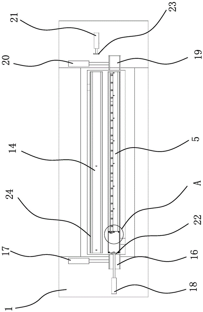
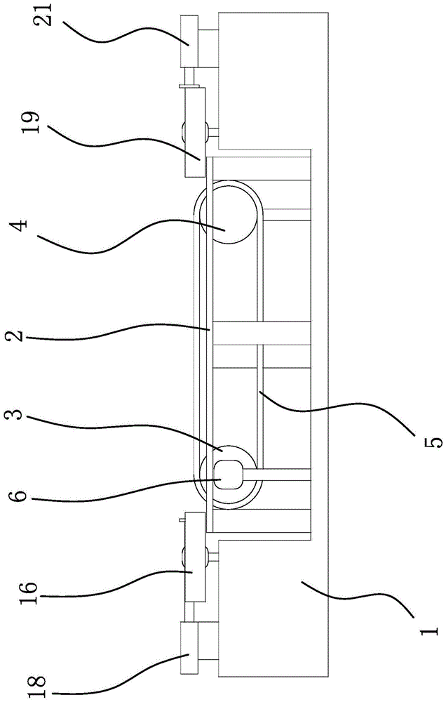
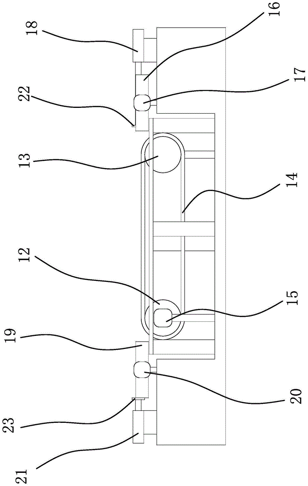
[0037] Such as figure 1 , figure 2 and image 3 As shown, an aging device for a charger includes a frame 1 , a workbench 2 fixed on the frame 1 , and an aging car set on the workbench 2 . Wherein, one side of the workbench 2 is provided with a transport mechanism capable of transporting aging vehicles from one end of the workbench 2 to the other end, and the other side of the workbench 2 is provided with a turning mechanism capable of resetting the tooling plate 9 .

[0038] Such as figure 2 and image 3 As shown, specifically, the transportation mechanism includes a driving roller-3, a driven roller-4 and a transmission belt-5 sleeved between the driving roller-3 and the driven roller-4, and a servo motor is horizontally fixed on the workbench 2 16. The output shaft of the servo motor 16 is connected with the driving roller 13 through a coupling. The driving roller 13 and the driven roller 4 are set on the workbench 2 through the rotating shaft, bearing and bearing seat...

Embodiment 2

[0051] The structure and principle of this embodiment are basically the same as that of Embodiment 1. The difference is that in Embodiment 1, the positioning structure includes grooves 1 and 2 on both sides of the burn-in disk and fixed on the support partition. Positioning plate one and positioning plate two; and in the second embodiment, the positioning structure includes grooves one and two on both sides of the burn-in plate and positioning plate one and positioning plate two fixed on the support partition, The gap formed between the positioning plate 1 and the positioning plate 2 is used for installing the burn-in disk. Wherein, positioning plate one includes vertical plate one and horizontal plate one horizontally fixed on the top of vertical plate one, the lower plate surface of vertical plate one is fixed on the upper surface of supporting partition, and the lower plate surface of horizontal plate one is fixed on vertical plate one One side of the horizontal plate protr...


PUM


Abstract

The invention provides an aging device for a charger, belongs to the technical field of testing, and solves the problem that an aging test cannot be performed on the charger efficiently in the prior art. The aging device for the charger comprises a rack, a working table and an aging trolley, wherein the working table is provided with a conveying mechanism; the conveying mechanism comprises a driving roller I, a driven roller I and a driving belt I, and an aging line is fixed on the driving belt I; the working table is provided with a rotary mechanism which comprises a driving roller II, a driven roller II and a driving belt II; the aging trolley comprises a box, a partition board capable of dividing a cavity into a cooling cavity and a loading cavity is fixed in the box, support partition boards are fixed in the loading cavity, loading boxes are fixed on each support partition board, test turnover discs are arranged on the loading boxes and comprises disc bodies, jacks are formed in each disc body, and sockets are fixed in cavities. The aging device for the charger has the advantage that the aging test can be performed on the charger more conveniently and efficiently.

Description

technical field [0001] The invention belongs to the technical field of testing, and relates to an aging device, in particular to an aging device for a charger. Background technique [0002] During the use of polymer materials, due to the combined effects of heat, oxygen, water, light, microorganisms, chemical media and other environmental factors, the chemical composition and structure of polymer materials will undergo a series of changes, and the physical properties will also change accordingly. Bad, such as hardening, stickiness, brittleness, discoloration, loss of strength, etc. These changes and phenomena are called aging. In order to ensure that the processed products have good anti-aging ability, aging tests are required before production. [0003] Aging test mainly refers to thermal oxygen aging test for rubber, plastic products, electrical insulation materials and other materials; or ventilation aging test for electronic parts and plasticized products. At present, ...

Claims


Application Information

Patent Timeline
Patent Type & Authority Patents(China)
IPC IPC(8): G01N17/00
Inventor 李晓龙唐文孝何思求
Owner 嘉兴市蓝欣电子科技有限公司
Why Eureka
Try Eureka