Radar radiation source identification method based on phase noise unintentional modulation characteristic

A phase noise, unintentional modulation technology, applied in the field of radar radiation source identification, can solve the problem of low recognition rate, achieve the effect of accurate identification model, accurate radar radiation source identification and judgment, and good radar radiation source identification and classification effect

Inactive Publication Date: 2015-07-29
HARBIN INST OF TECH
View PDF0 Cites 29 Cited by
  • Summary
  • Abstract
  • Description
  • Claims
  • Application Information

AI Technical Summary

Problems solved by technology

[0004] In order to solve the problem that the identification rate of the exi

Method used


Image

  • Radar radiation source identification method based on phase noise unintentional modulation characteristic
  • Radar radiation source identification method based on phase noise unintentional modulation characteristic
  • Radar radiation source identification method based on phase noise unintentional modulation characteristic

Examples


specific Embodiment approach 1

[0022] Specific embodiment one: a radar radiation source identification method based on phase noise unintentional modulation features, comprising the following steps:

[0023] Step 1: According to the structure of the phase-locked frequency synthesizer in the radar transmitter system, the phase noise model generated by the phase-locked frequency synthesizer is established as follows:

[0024] s ( t ) = sin ( 2 π f c t ) + Σ m ′ Δ φ m ′ 2 sin [ 2 π ( f c + ...

specific Embodiment approach 2

[0030] Specific implementation mode two: described in this implementation mode

[0031] The phase noise model formula (7) concrete steps that the phase noise model formula (7) that the described setting-up phase-locked frequency synthesizer of step 1 produces are as follows:

[0032] Phase noise can be seen as the phase of the original signal with frequency f m The sine wave modulation of , taking the single frequency signal as an example, let the frequency of the original signal be f c , the signal after adding a single phase noise is expressed as

[0033] s(t)=sin(2πf c t+Δφ(t))=sin(2πf c t+Δφ m sin(2πf m t)) (1)

[0034] Among them, Δφ(t) represents the modulation signal, Δφ m is the phase modulation coefficient, t is the pulse width, f m is the modulation signal frequency;

[0035] Expand the above formula to

[0036] s(t)=sin(2πf c t)cos(Δφ m sin(2πf m t))+cos(2πf c t)sin(Δφ m sin(2πf m t)) (2)

[0037] The expressions of (3) and (4) in the Bessel functio...

specific Embodiment approach 3

[0049] Specific implementation mode three: the described in this implementation mode

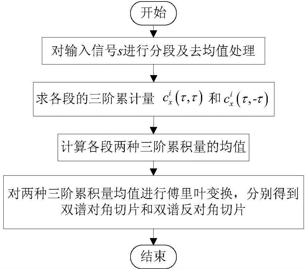
[0050] Calculate the bispectral diagonal slice feature multiple times described in step 2 to obtain the bispectral diagonal slice sample composition matrix A 1 The specific steps are as follows:

[0051] Step 2.1.1: The received signal s(t) is abbreviated as s, and it is segmented and processed. Each segment takes M data, which is divided into P segments, and the data in each segment is de-averaged:

[0052] x i ( n ′ ) = s i ( n ′ ) - 1 M Σ n ′ = 1 M s i ...


PUM


Abstract

The invention discloses a radar radiation source identification method based on phase noise unintentional modulation characteristic, relates to an identification method of a radar radiation source, and aims to solve the problem that the identification rate of an existing radiation source identification method based on phase noise is not high. The method disclosed by the invention comprises the following steps of analyzing the structure of a phase-lock frequency synthesizer in a radar transmitter system; building a model of phase noise generated by the phase-lock frequency synthesizer; calculating a bispectrum diagonal slice characteristic and a bispectrum non-diagonal slice characteristic; forming a characteristic matrix Y by using a bispectrum diagonal slice characteristic matrix A1 and a bispectrum non-diagonal slice characteristic matrix B1; performing PCA (Principal Component Analysis) dimensional reduction and building a type-known transmitter vector machine model; identifying a transmission signal of a type-unknown transmitter by utilizing the built vector machine model so as to realize the identification of a radar radiation source. The method disclosed by the invention is applicable to the identification of the radar radiation source.

Description

technical field [0001] The invention relates to a method for identifying a radar radiation source. Background technique [0002] In the early identification of radiation sources, the conventional characteristic parameters and the intra-pulse modulation characteristics of the radiation source signal were mainly analyzed, and the analysis of intra-pulse modulation characteristics mainly focused on the intentional modulation characteristics in the signal pulse. Later, people realized that feature extraction based on intra-pulse intentional modulation could not adapt to today's increasingly complex battlefield environment and various types of new radars with increasingly advanced configurations, because most of the new radars have complex and multiple working modes and modulation modes, and their pulse The intentional modulation can be changed arbitrarily, and it is difficult for non-cooperating parties to detect its radar working system. In this case, the research on the chara...

Claims


Application Information

Patent Timeline
IPC IPC(8): G06F19/00G01S7/40
Inventor 赵雅琴张姣吴龙文任光辉
Owner HARBIN INST OF TECH
Why Eureka
Try Eureka