
Space synchronous positioning and information recording system based on three-dimensional real scene model

A real-world model and synchronous positioning technology, which is applied in 3D modeling, image data processing, instruments, etc., can solve the problems of insufficient visualization of CAD expanded drawings, no solution, single recorded information, etc. Ease of management and improved efficiency

Active Publication Date: 2015-07-29
CENT RES INST OF BUILDING & CONSTR CO LTD MCC GRP
View PDF2 Cites 19 Cited by
  • Summary
  • Abstract
  • Description
  • Claims
  • Application Information

AI Technical Summary

Problems solved by technology

However, this method still has many shortcomings. First, there is a certain gap between the CAD model and the real situation of the observed object, and the information that requires high precision cannot be accurately reflected from the model; and the visualization of the two-dimensional effect of the CAD expansion diagram is not enough. High, the recorded information is single, currently it can only be used to record image information, there is a lot of room for improvement; at the same time, the technical threshold of this method is high, the price is expensive, and it has not become a popular solution

Method used


Image

  • Space synchronous positioning and information recording system based on three-dimensional real scene model
  • Space synchronous positioning and information recording system based on three-dimensional real scene model
  • Space synchronous positioning and information recording system based on three-dimensional real scene model

Examples


Embodiment Construction

[0032] Below we will further illustrate the present invention in conjunction with accompanying drawing and specific example:

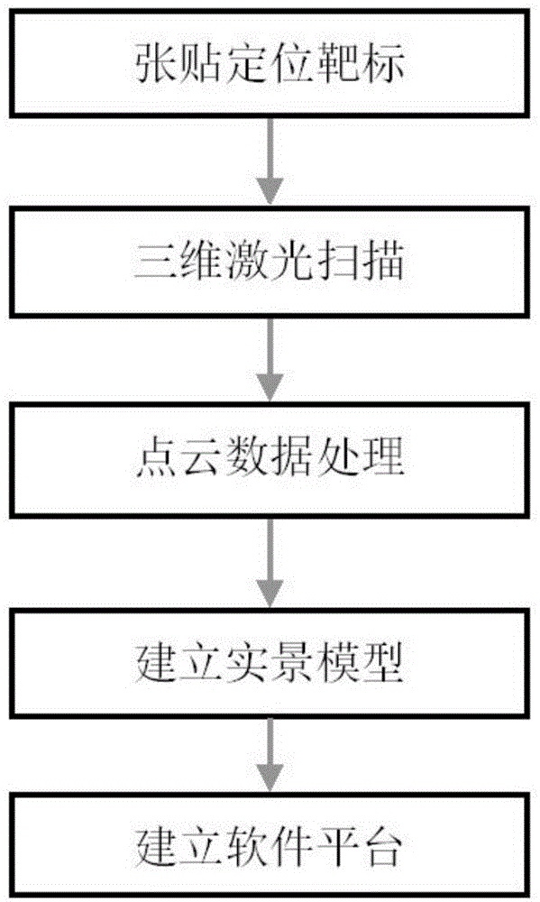
[0033] Such as figure 1 As shown, the process of establishing the 3D real scene model of the observed object is divided into the following five steps:

[0034] 1. Post positioning targets: The total number of posted targets depends on the number of scanning stations required by the scanned object. Each station needs to paste more than 5 targets (not collinear, not coplanar) on the scanned object, and two stations Between scans, there need to be at least two common targets. These targets will be used as feature points for point cloud stitching and feature points for establishing a spatial coordinate system.

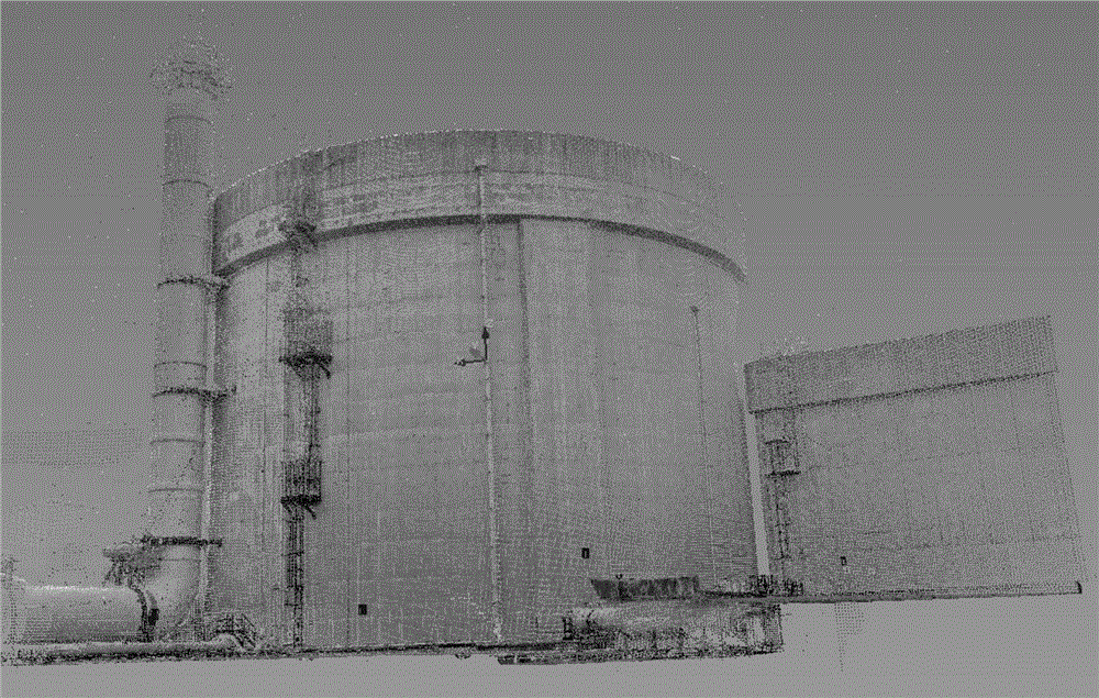
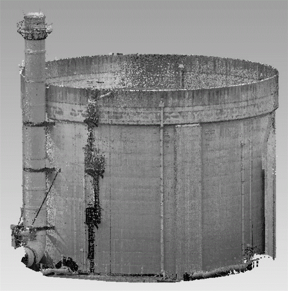
[0035] 2. Three-dimensional laser scanning: the three-dimensional laser scanner is used to collect the spatial information of the surface of the measured object, which is the data basis for establishing a three-dimensional real scene model later....


PUM


Abstract

The invention relates to a space synchronous positioning and information recording system, which can be mainly applied to carrying out positioning on the located position in a three-dimensional real scene model when information is acquired in a building structure and recording the acquired information at the corresponding position. According to the system provided by the invention, three-dimensional point cloud data of the surface of an observed object is acquired at first through a three-dimensional laser scanner, a three-dimensional real scene model with three-dimensional coordinate information is acquired through processing the three-dimensional point cloud data by point cloud data processing software and reverse modeling software, and a computer terminal software platform is established based on the three-dimensional real scene model; and the three-dimensional real scene software platform of the computer terminal is connected to a universal cradle head positioning instrument, thereby being capable of aiming at any positions on the observed object. The positioning instrument takes a universal cradle head and a laser emission instrument as a basis, the universal cradle head positioning instrument capable of carrying an information acquisition instrument is established, and a data processing, storage and transmission module is arranged inside at the same time. Finally, the universal cradle head positioning instrument and the three-dimensional real scene software platform carry out matching on the three-dimensional real scene model and the actual space according to a space matching method, thereby becoming a system with space synchronous positioning and information recording functions.

Description

technical field [0001] The invention relates to a system for spatial synchronous positioning and information recording, in particular to a system which can be applied to the field of buildings and structures to help the positions captured by information collection equipment to realize synchronous positioning and information recording in a three-dimensional real scene model. technical background [0002] At present, in engineering inspection, although it is possible to remotely capture defects such as cracking, exposed steel bars, heat leakage, and deformation on large buildings through image acquisition instruments, thermal imagers, and deformation monitoring instruments, the real coordinate system of the defect location Positioning and marking, but there is no good solution, which brings great difficulties to subsequent improvement, repair, monitoring and other work. For example, as far as image acquisition is concerned, when the captured defects are small, and the building...

Claims


Application Information

Patent Timeline
IPC IPC(8): G06T17/00
Inventor 韩达光张兴斌林松涛张晓旭李学飞梁宁博杨永光马晓鑫马鹏飞
Owner CENT RES INST OF BUILDING & CONSTR CO LTD MCC GRP
Learn More