A frequency calibration device and frequency synthesizer

A frequency synthesizer and frequency calibration technology, applied in the microwave field, can solve the problems of high use efficiency, high calibration accuracy, and low cost, and achieve the goal of improving calibration efficiency and calibration accuracy, high calibration accuracy, and high calibration efficiency Effect

Active Publication Date: 2017-09-19
CHENGDU SIMON ELECTRONICS TECH
View PDF7 Cites 1 Cited by
  • Summary
  • Abstract
  • Description
  • Claims
  • Application Information

AI Technical Summary

Problems solved by technology

[0007] However, this method is expensive, requires a high-precision test instrument, and also needs to build a test and adjustment environment, which is troublesome to use and low in efficiency.
[0008] To sum up, the existing test devices or methods cannot achieve the goals of high calibration accuracy, low cost, convenient use, and high use efficiency at the same time.

Method used


Image

  • A frequency calibration device and frequency synthesizer
  • A frequency calibration device and frequency synthesizer
  • A frequency calibration device and frequency synthesizer

Examples


Embodiment 1

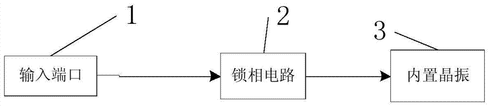
[0043] figure 1 Shown is a frequency calibration device shown in Embodiment 1 of the present invention, including:

[0044] The input port 1 is used to receive and output a reference signal; wherein the reference signal is a predetermined signal that has been measured for frequency accuracy;

[0045] The phase locking circuit 2 is configured to receive the reference signal output from the input port, and lock the frequency of the output signal of the built-in crystal oscillator of the frequency synthesizer to the frequency of the reference signal.

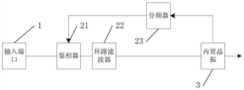
[0046] In one embodiment, specifically, see figure 2 , the phase lock circuit includes a phase detector 21, the input end of the phase detector 21 is connected to the input port 1, the output end of the phase detector 21 is connected to the input end of the loop filter 22, the loop filter The output end of the road filter 22 is connected to the built-in crystal oscillator 3, and the built-in crystal oscillator is also connected ...

Embodiment 2

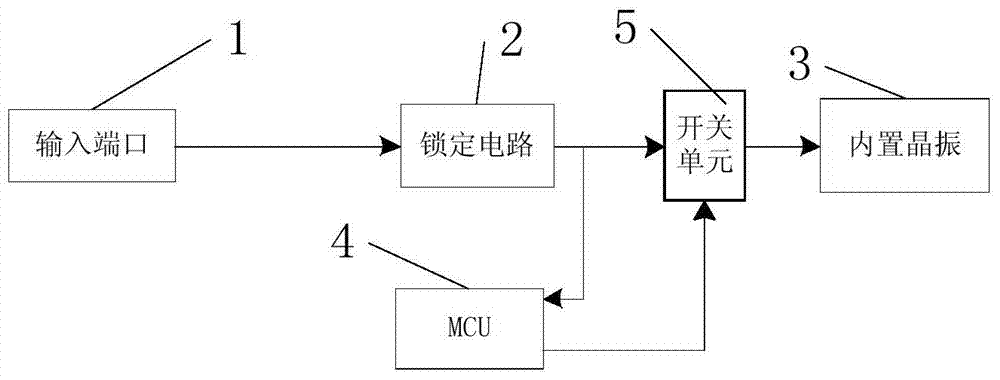
[0051] image 3 Shown is a frequency calibration device shown in Embodiment 2 of the present invention, including the content in Embodiment 1, and also includes a switch unit 5, MCU4,

[0052] The first moving end of the switch unit 5 is connected to the loop filter 22 , the second moving end is connected to the signal output end of the MCU 4 , and the fixed end is connected to the built-in crystal oscillator 3 .

[0053] Described MCU4 signal receiving terminal is connected with the output terminal of described loop filter 22, is used for continuously receiving the voltage value that 1 described loop filter 22 output terminals output, if described voltage value is all identical continuously J times, The MCU4 stores the same voltage value for J consecutive times as a locking voltage, where I≥5, 4≤J≤I;

[0054] Otherwise, the MCU4 calculates the corresponding N value according to the frequency of the built-in crystal oscillator 3 and the frequency of the reference signal, contro...

Embodiment 3

[0065] Figure 5 Shown is a frequency calibration device shown in Embodiment 3 of the present invention, including the content in Embodiment 2, and also includes a detection unit 6, the input end of the detection unit 6 is connected to the input port, and the output end is connected to the MCU4, configured to receive the reference signal, and convert the reference signal into a detection voltage output;

[0066] The MCU4 is also used to receive the detection voltage signal, compare it with a preset threshold voltage, and judge whether the detection voltage signal can be input into the phase-locked circuit 2, and if so, control the switch unit 5 to switch to the first moving end.

[0067] The MCU4 stores the preset threshold voltage.

[0068] In one embodiment, specifically, see Figure 6 , the output end of the detector 61 is connected to the input end of the A / D converter 7, since the reference signal is generally a relatively large power signal, when an external signal is...


PUM


Abstract

The invention discloses a frequency calibration device, comprising: an input port for receiving and outputting a reference signal; wherein the reference signal is a predetermined signal whose frequency accuracy has been measured; a phase-locked circuit for receiving the input port The output reference signal locks the frequency of the output signal of the built-in crystal oscillator of the frequency synthesizer to the frequency of the reference signal. A frequency calibration device of the present invention can complete the frequency calibration of the crystal oscillator by inputting a predetermined signal measured by the frequency accuracy into the calibration circuit through phase-locking. The device is low in cost, simple and fast in use. The calibration work can be completed efficiently.

Description

technical field [0001] The invention relates to the microwave field, in particular to a frequency calibration device and a frequency synthesizer. technical background [0002] With the development of electronic equipment, electronic systems put forward higher and higher requirements for frequency sources, and the microwave phase-locked frequency source technology of high-quality microwave frequency integrated generators through phase-locked technology has also been greatly developed. [0003] A general phase-locked frequency source uses a built-in constant temperature crystal oscillator as the clock reference, and the output microwave frequency signal is related to the reference in a phase-locked manner, and its frequency is N times the reference frequency (N is a real number greater than 0). The accuracy of the output frequency obtained by phase locking is also equal to the frequency accuracy of the clock reference. When the frequency of the constant temperature crystal os...

Claims


Application Information

Patent Timeline
Patent Type & Authority Patents(China)
IPC IPC(8): H03L7/18H03L7/085
Inventor 王崔州张泉杨晓东吴洋
Owner CHENGDU SIMON ELECTRONICS TECH
Why Eureka
Try Eureka