Coupling bodies for synchronizing devices of motor vehicle gear transmissions

A technology for gear transmissions and motor vehicles, applied in the direction of mechanical drive clutches, clutches, mechanical equipment, etc., can solve the problems of high manufacturing costs and achieve the effect of avoiding cutting processing

Inactive Publication Date: 2017-08-01
SCHAEFFLER TECH AG & CO KG
View PDF1 Cites 0 Cited by
  • Summary
  • Abstract
  • Description
  • Claims
  • Application Information

AI Technical Summary

Problems solved by technology

Manufacturing costs are therefore high in some designs

Method used


Image

  • Coupling bodies for synchronizing devices of motor vehicle gear transmissions
  • Coupling bodies for synchronizing devices of motor vehicle gear transmissions
  • Coupling bodies for synchronizing devices of motor vehicle gear transmissions

Examples


Embodiment Construction

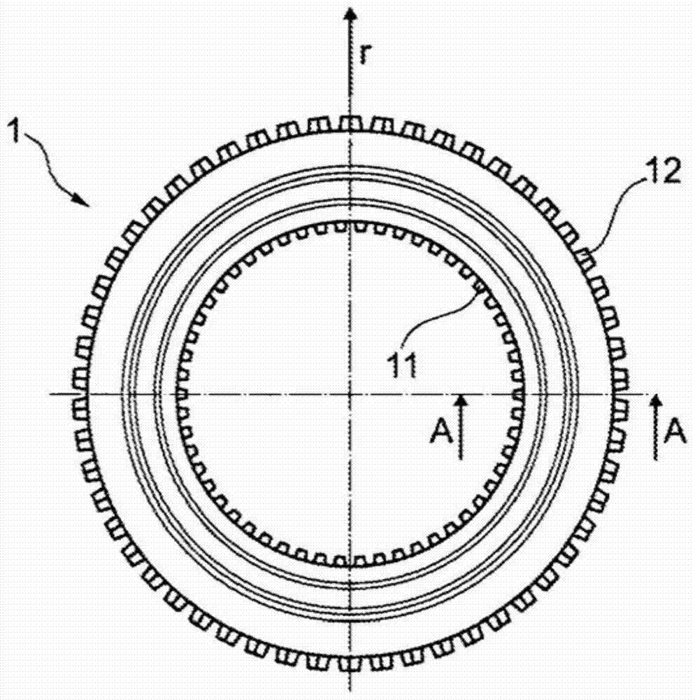
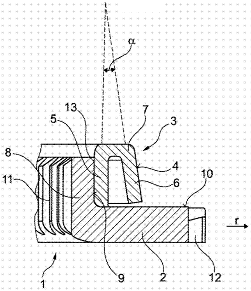
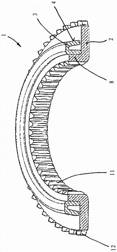
[0027] exist Figures 1 to 3 A first embodiment of the present invention is schematically shown in FIG. A coupling body 1 is shown in different views, which belongs to a synchronization device of a gear transmission of a motor vehicle. The coupling body 1 is designed in two parts.

[0028] A part of the coupling body 1 is formed by the coupling disc section 2, which is in the radial section (for this best see figure 2 ) has an L-shaped profile. The second part of the coupling body 1 is formed by a friction cone 3 which has a friction cone surface 4 and is connected to the coupling disk section via a permanent connection 13 .

[0029] The two parts 2 and 3 can be produced by simple production technology processes. First, the ring-shaped part is punched or punched out of the sheet metal strip. The parts 2 and 3 shown are produced by shaping, die-casting and / or deep-drawing, wherein machining by cutting can be dispensed with. The two parts 2 and 3 are thus connected to eac...


PUM


Abstract

The invention relates to a clutch body (1) for a synchronization mechanism of an automotive variable speed gear transmission, comprising an annular clutch disk portion (2), a friction cone (3) being arranged on the clutch disk portion (2) and having a friction cone surface (4) for the frictional contact with at least one synchronizer ring. In order to simplify production of the clutch body and render it more cost-effective, the friction cone (3) is formed by a separate component which is arranged on the clutch disk portion (2) and is permanently connected thereto.

Description

technical field [0001] The invention relates to a coupling body of a synchronizing device for a gear transmission of a motor vehicle, which comprises an annular coupling disc section, wherein friction cones are arranged on the coupling disc section for friction against at least one synchronizing ring. The ground contact has a friction cone. Background technique [0002] Coupling bodies of the conventional type are known, for example, from DE 10 2006 056 487 A1. Such coupling bodies are required in synchronizers which are used in manual transmissions according to the principle of gear shifting, that is to say the classic case of application is a mechanical manual transmission of a motor vehicle. The synchronizer decisively simplifies gear changing. The coupling body and further synchronizing components are used to compensate for the different rotational speeds of the shaft and gearwheel during the shifting process. The coupling body is arranged between the idler gear and t...

Claims


Application Information

Patent Timeline
Patent Type & Authority Patents(China)
IPC IPC(8): F16D23/06
CPCF16D23/06F16D2023/0625
Inventor 瓦莱丽·曼多布鲁诺·舍尔布胡贝特·克雷斯
Owner SCHAEFFLER TECH AG & CO KG
Why Eureka
Try Eureka