Arch breaking unit and stock bin

A technology for breaking arches and silos, which is applied in the field of silos equipped with the arch breaking unit, which can solve the problems of increasing operating costs, heavy maintenance workload, and reducing the discharge efficiency of silos, so as to increase the service life of equipment , Prevent rigid breakage and enhance the effect of arch breaking

Inactive Publication Date: 2015-08-05
车战斌
View PDF0 Cites 4 Cited by
  • Summary
  • Abstract
  • Description
  • Claims
  • Application Information

AI Technical Summary

Problems solved by technology

Most of the components in the moving parts in the prior art are rigidly connected, and the rigidly connected components get stuck after encountering the above-mentioned huge resistance from the material, which leads to the overall stop of the arch breaking device and cannot achieve the continuous arch breaking effect
At the same time, the motors and other devices that drive the moving parts generate huge loads, resulting in overloading of the motors and even damage to the motors
In addition, the rigidly connected components have been operating for a long time under the condition of constantly changing arching resistance of the material, and the moving parts are also easily damaged. The maintenance workload is heavy, which increases the operating cost and reduces the discharge efficiency of the silo.

Method used


Image

  • Arch breaking unit and stock bin
  • Arch breaking unit and stock bin
  • Arch breaking unit and stock bin

Examples


Embodiment approach 1

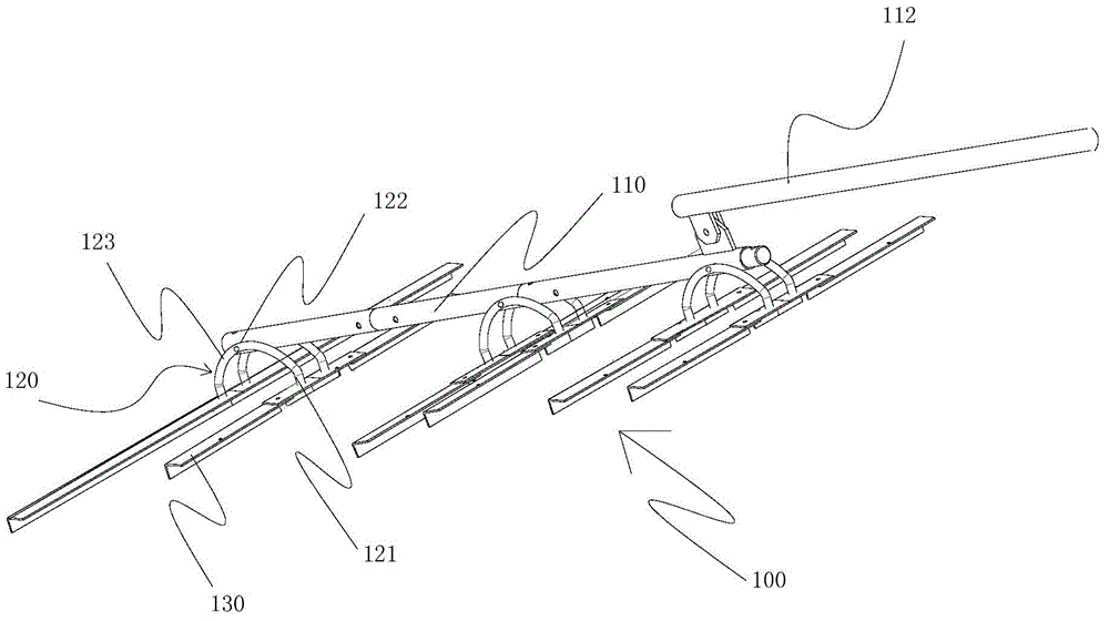
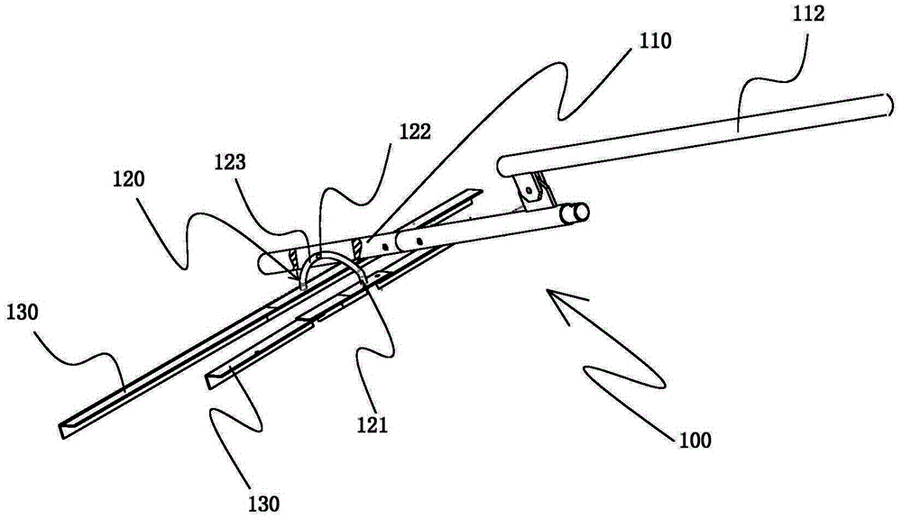
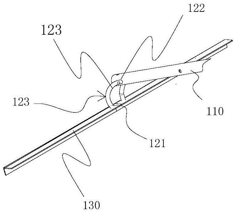
[0063] figure 1 It shows a schematic structural diagram of an embodiment of the arch breaking unit of the present invention;

[0064] Such as figure 1 As shown, the arch breaking unit 100 of the present invention includes a connecting rod 110; the connecting rod 110 is pivotally connected with one or more connecting pieces 120 in the axial direction, and at least one cantilever end 121 of the connecting piece 120 is connected with a dial The material arm 130; the material arm 130 is set at an angle with the connecting rod 110; when the connecting rod 110 moves in the axial direction, under the action of arching resistance, the cantilever end 121 of the connecting piece 120 is relative to the connecting piece 120 and the connecting rod 120. The pivot point 122 of the rod 110 is angularly displaced to adjust the arch-breaking resistance of the shifting arm 130 .

[0065] The working principle of the present invention is that during the arch breaking process of the arch breakin...

Embodiment approach 2

[0075] Such as image 3 As shown, the second embodiment of the present invention is basically the same as the previous embodiment, the only difference being that the shifting arm 130 and the connecting member 120 are pivotally connected within the movement plane of the shifting arm 130, and the shifting arm The other end of 130 forms a free end 131 that can rotate around the pivot point 137 , and the free end 131 constitutes the rotational degrees of freedom of the shifting arm 130 in different planes. When the arching state of the material in the silo is serious, and the material shifting arm 130 encounters a relatively large arching resistance, the free end 131 of the material shifting arm 130 rotates around the pivot point 137 to avoid the arching bridge. A rotation degree of freedom is added to the shifting arm 130, fundamentally preventing the rigidity of the shifting arm 130 from being damaged. Simultaneously, the free end 131 of the driving arm 130 effectively disturbs...

Embodiment approach

[0087] The present invention also proposes a silo 300, which includes a discharge port and is formed at the bottom of the silo 300; it is characterized in that: the bottom of the silo 300 is provided with one or more arch breaking units 100, and the arch breaking units The connecting rod 110 of 100 is arranged along the inner wall surface of the bottom of the silo, and is driven to reciprocate by the driving mechanism 112. The material shifting arm 130 reciprocates with the connecting rod 110, and the material in the silo 300 is moved along the bottom of the silo. The inner surface of the inner wall is dialed to the discharge port of the feed bin 300.

[0088] The present invention utilizes the above-mentioned arch-breaking unit to perform arch-breaking and exporting functions on the materials stored in the silo 300 during discharge, thereby ensuring the smooth discharge of the silo 300 . Moreover, by effectively reducing the breakage rate of the arch breaking unit 100, the br...


PUM


Abstract

An arch-breaking unit (100) comprising a connecting rod (110) actuated into a reciprocating movement by an actuating mechanism (112). The connecting rod (110) is connected along the axial direction to one or more connecting elements (120). The connecting elements (120) are pivotally connected to the connecting rod (110). Material-paddling arms (130) are connected to at least one cantilever end (121) of the connecting elements (120). The material-paddling arms (130) are arranged at an angle with the connecting rod (120). When the connecting rod (120) is moving in the axial direction, under the effect of an arching resistance, the cantilever ends (121) of the connecting elements (120) connected to the material-paddling arms (130) generate an angular displacement relative to where the connecting elements (120) and the connecting rod (110) are pivotally connected, thus regulating an arch-breaking resistance exerted on the material-paddling arms (130). The arch-breaking unit increases the freedom of movement of the material-paddling arms, reduces the rate of wear, and extends service life. Also disclosed is a material chamber (300) equipped with the arch-breaking unit (100).

Description

technical field [0001] The invention relates to an arch-breaking unit for a silo for loose materials, and a silo equipped with the arch-breaking unit. Background technique [0002] The silo is used to store grain, fertilizer, biomass fuel, coal powder and other bulk materials, and has been widely used in the field of industry and agriculture. When the silo is unloading, the ideal situation is that the bulk particles stored in it can be smoothly and uniformly discharged from the outlet of the silo. However, in the actual silo unloading process, not only the phenomenon that the bulk particles cannot be completely discharged, but also abnormal phenomena such as blockage often occur. This blocking phenomenon is mainly due to the fact that the loose particles are easy to form an arch structure. [0003] At present, the moving arch breaking method is a commonly used arch breaking method. The motion arch breaking method is to set a moving part (moving arm or blade) inside the si...

Claims


Application Information

Patent Timeline
Patent Type & Authority Applications(China)
IPC IPC(8): B65D88/64
CPCB65D88/68B65D88/64
Inventor 车战斌
Owner 车战斌
Why Eureka
Try Eureka