Function coordination machine

A technology for coordinating machines and functions, applied in the direction of electromechanical devices, electrical components, etc., can solve the problems of underutilization, waste of motor rotational kinetic energy, etc., and achieve the effect of reducing external energy input

Inactive Publication Date: 2015-08-05
杨培应
View PDF6 Cites 2 Cited by
  • Summary
  • Abstract
  • Description
  • Claims
  • Application Information

AI Technical Summary

Problems solved by technology

Existing generators and motors exist independently, and the rotational kinetic energy generated by the motor is usually wasted and not fully utilized

Method used


Image

  • Function coordination machine
  • Function coordination machine

Examples


Embodiment Construction

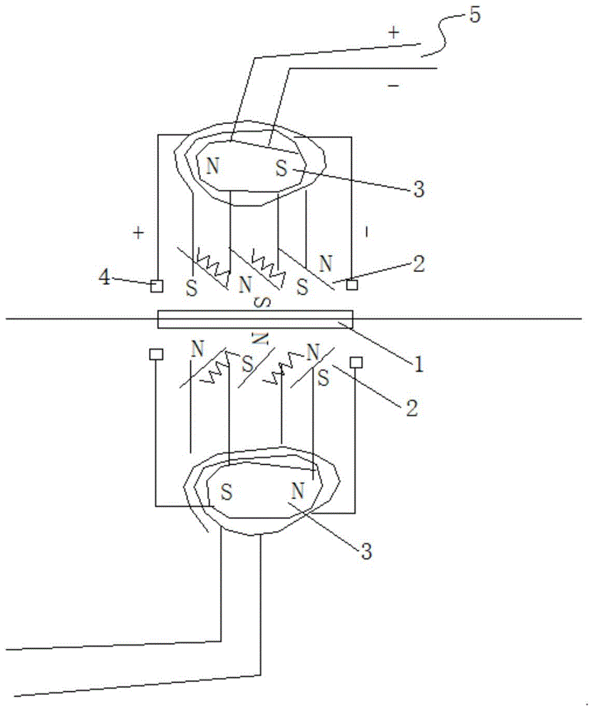
[0014] Such as figure 1 As shown, the present invention provides a function coordination machine, which includes a rotor 1 , a first stator 2 and a second stator 3 . Among them, the rotor 1 is composed of a magnet and a cylindrical iron core, the two ends of which are S poles and N poles respectively, and several grooves are opened on the outer surface of the cylindrical iron core, and the coil windings are wound in the grooves. The first stator 2 is composed of a first circular magnet, a coil wound on the first circular magnet and a connection terminal 4 , and the rotor 1 is arranged on the central axis of the first stator 2 . The second stator 2 is composed of a second circular magnet and coils wound on the second circular magnet at even intervals, and the second stator 2 is connected to an external power supply device through a wire 5 .

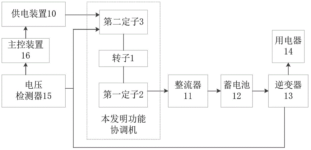
[0015] Such as figure 2 As shown, when the function coordination machine of the present invention is used to supply power to external ...


PUM


Abstract

The utility model relates to a function coordination machine comprising a rotor, a first stator, and second stators. The rotor is formed by a magnet and a cylindrical iron core and an S pole and an N pole are arranged at the two ends; a plurality of grooves are formed in the outer surface of the cylindrical iron core; and coil windings wind around the grooves. The first stator consists of a first circular-ring-shaped magnet, a coil winding around the first circular-ring-shaped magnet, and wiring terminals; and the rotor is arranged at the central axis of the first stator. The second stators are formed by second circular-ring-shaped magnets and coils winding around the second circular-ring-shaped magnets uniformly at intervals; and the second stators are connected with external power supply equipment by leads. The function coordination machine has the following beneficial effects: the rotation kinetic energy generated by the motor during working can be fully utilized, thereby preventing wasting and achieving an objective of external energy input reduction.

Description

technical field [0001] The invention relates to a power device, in particular to a function coordination machine. Background technique [0002] A generator is a mechanical device that converts other forms of energy into electrical energy. It is driven by a water turbine, steam turbine, diesel engine or other power machinery, and converts the energy generated by water flow, air flow, fuel combustion or nuclear fission into mechanical energy and transmits it to the generator. Converted to electrical energy by a generator. A motor is a device that converts electrical energy into mechanical energy. It uses the stator winding to generate a rotating magnetic field and acts on the rotor to form a magnetoelectric force rotating torque. Existing generators and motors exist independently, and the rotational kinetic energy generated by the motor during operation is usually wasted and not fully utilized. Contents of the invention [0003] In order to solve the above-mentioned probl...

Claims


Application Information

Patent Timeline
Patent Type & Authority Applications(China)
IPC IPC(8): H02K16/04
Inventor 杨培应
Owner 杨培应
Why Eureka
Try Eureka