Motor control device

A control device and motor technology, applied in the direction of motor control, control system, electrical components, etc., can solve problems such as mechanical damage, and achieve the effects of improving reliability, avoiding mechanical damage, and easy positioning

Active Publication Date: 2015-08-05
SANYO DENKI CO LTD
View PDF5 Cites 6 Cited by
  • Summary
  • Abstract
  • Description
  • Claims
  • Application Information

AI Technical Summary

Problems solved by technology

If the positional deviation becomes large...

Method used


Image

  • Motor control device
  • Motor control device
  • Motor control device

Examples


Embodiment approach 1

[0051] Configuration of the motor control device 100

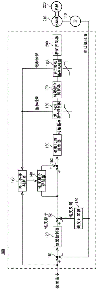
[0052] figure 1 It is a block diagram of the motor control device of Embodiment 1. The motor control device 100 has: a position controller 120, a speed calculator 130, a speed integral controller 140, a speed proportional controller 150, a first torque command limiter 160, a torque command filter 170, a second torque command limiter device 180, stop condition determiner 190 and torque controller 200.

[0053] The deviation between the position command and the motor position is input to the position controller 120 . The position controller 120 outputs a speed command based on the input deviation.

[0054] The motor position is input to the speed calculator 130 . The speed calculator 130 outputs speed feedback based on the input motor position.

[0055] The deviation between the speed command and the speed feedback is input to the speed integral controller 140 . The speed integral controller 140 integrates the input d...

Embodiment approach 2

[0089] Configuration of the motor control device 300

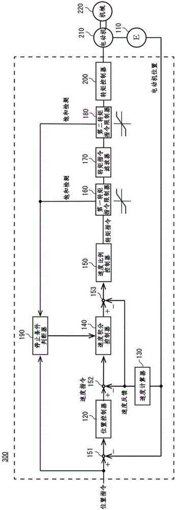
[0090] figure 2 It is a configuration diagram of another motor control device according to the second embodiment. The motor control device 300 uses IP control. The constituent elements of the motor control device 300 and figure 1 The motor control device 100 shown is the same. Therefore, for figure 1 The same constituent elements are assigned the same reference numerals.

[0091] The motor control device 300 differs from the motor control device 100 in the following points. That is, in the motor control device 300 , the bypass circuit of the speed integral controller 140 directly connecting the addition point 152 and the addition point 153 does not exist. In addition, in the motor control device 300 , speed feedback is performed on the addition point 153 .

[0092] Operation of the motor control device 300

[0093] overall action

[0094] First, the position command and the motor position of the motor 210 detec...


PUM


Abstract

The invention provides a motor control device which can suppress speed overshoot and output of an overlarge torque in deceleration of a motor. It's hard to cause offset of the motor, so that positioning of the motor can be easily carried out. The provided motor control device has a first torque instruction limiter (160) and a second torque instruction limiter (180). When the magnitude of the torque exceeds a set scope, the magnitude will be limited in the set scope and saturation detection can be output. A stop condition judging machine (190) monitors changing states of a position instruction. When the position instruction changes, an integral action of a speed integral controller is stopped according to the saturation detection of the first torque instruction limiter. When the position instruction does not change, the integral action of the speed integral controller is stopped according to the saturation detection of the second torque instruction limiter.

Description

technical field [0001] The invention relates to a motor control device. Background technique [0002] A motor control device that is difficult to cause position deviation during motor oscillation (vibration) and thus can easily perform motor positioning. When the operating value in the control system is saturated, anti-saturation processing is performed to prevent the output value of the speed integral controller from becoming is too big. Anti-windup processing is divided into two methods, a method using feedback and a method of stopping the speed integral controller. [0003] Figure 4 It is a diagram showing an example of a conventional motor control device that uses feedback for anti-saturation processing. [0004] The motor control device 30 multiplies the difference between the input to the torque command limiter 32 and the output from the torque command limiter 32 by a feedback gain multiple (K times) using the feedback controller 34 . Feedback the difference multip...

Claims


Application Information

Patent Timeline
IPC IPC(8): H02P29/00
Inventor 井出勇治山﨑悟史北原通生
Owner SANYO DENKI CO LTD
Why Eureka
Try Eureka