Dynamic visual acuity detecting method

A detection method and visual acuity technology, applied in the field of dynamic visual acuity detection, can solve the problems of visual mark deformation, cumbersome equipment, and inability to use clinical actual inspection, and achieve the effect of simple operation process and high inspection efficiency

Active Publication Date: 2015-08-12
PEKING UNIV THIRD HOSPITAL +1
View PDF5 Cites 19 Cited by
  • Summary
  • Abstract
  • Description
  • Claims
  • Application Information

AI Technical Summary

Problems solved by technology

However, the equipment involved in this method is cumbersome and is only suitable for experimental research and cannot be used for clinical actual inspection; (2) laser light source projection method: replace the projection equipment with a laser light source with a wavelength of 633-670nm to project the letter visual mark onto Reflective mirror, the speed of the visual target can reach 150° / s. Due to the delay effect of the laser excitation time, the high-speed moving visual target will be deformed. The visual target in this method can only be a letter visual target, and the reflective mirror is still used Rotation to obtain dynamic visual targets, still need to set up a ring screen, which is only suitable for experimental research, not for clinical actual inspection; (3) Computer program combined with fluorescent screen display projection method: the dynamic visual target is obtained by combining computer programs with fluorescent screen monitors , does not require rotating mirrors and ring curtains, and has relatively loose requirements for equipment and inspection environments. Due to the restriction of the flicker effect of the fluorescent screen, the movement speed of the visual target is usually lower than 10° / s, and the highest can only reach 50° / s. It cannot cover the movement speed range (60° / s-150° / s) of common objects in daily life, so it cannot meet the needs of actual evaluation

Method used


Image

  • Dynamic visual acuity detecting method
  • Dynamic visual acuity detecting method
  • Dynamic visual acuity detecting method

Examples


Embodiment Construction

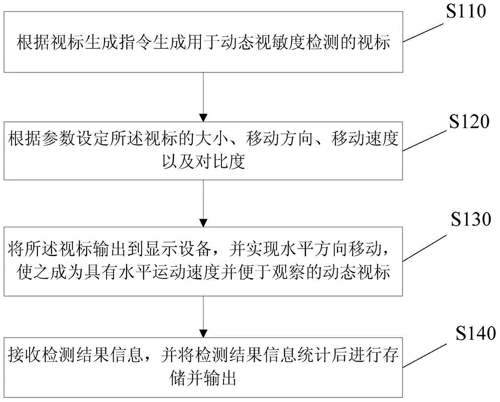
[0023] The embodiment of the present invention provides a dynamic visual acuity detection method, please refer to figure 1 , figure 1 It is a flowchart of a dynamic visual acuity detection method according to an embodiment of the present invention, and the method specifically includes the following steps:

[0024] Step S110: Generate an optotype for dynamic visual acuity detection according to the optotype generation instruction.

[0025] Step S120: Set the size, moving direction, moving speed and contrast (ie transparency) of the visual target according to the parameters.

[0026] Step S130: Output the optotype to the display device, and realize the horizontal movement, making it a dynamic optotype with horizontal movement speed and easy to observe.

[0027] Step S140: Receive the detection result information, store and output the detection result information after statistics.

[0028] Wherein, the optotype described in step S110 is an English letter optotype used for visu...


PUM


Abstract

The invention discloses a dynamic visual acuity detecting method. The method includes the steps that optotypes used for dynamic visual acuity detection are generated according to an optotype generating instruction; the sizes, the moving directions, the moving speed and the contrast ratios of the optotypes are set according to parameters; the optotypes are output to a display device and move in the horizontal direction to become dynamic optotypes which have horizontal motion speed and are convenient to observe; detection result information is received and is stored and output after statistics is carried out on the detection result information. Dynamic visual acuity evaluation is achieved in the process of observing the horizontal motion optotypes by an individual, and a motion visual acuity checking system taking visual acuity evaluation in the process of observing the horizontal motion optotypes from far to near by the individual as the main content is consummated; in addition, the checking method is concise in operation process and high in checking efficiency, equipment is simple and saves space, and the dynamic visual acuity detecting method is adaptive to actual requirements of clinical diagnosis and treatment and can be used for meticulously evaluating visual functions of drivers, sportsmen and other crowds with the high requirement for dynamic visual acuity.

Description

technical field [0001] The invention belongs to the technical field of psychophysical measurement of visual function of human eyes, and in particular relates to a dynamic visual acuity detection method. Background technique [0002] The minimum viewing angle that the human eye can distinguish is called visual acuity, which is commonly referred to as vision. The commonly used method for evaluating visual acuity is the visual acuity chart method. In this method, there is no relative movement between the visual target and the subject, and the test results reflect the static visual acuity of the subject. When there is relative movement between the visual target and the subject, the minimum visual angle that the subject's eye can distinguish is called dynamic visual acuity. Since most of the objects that individuals need to identify in life scenes are dynamic objects with a certain speed of movement, and activities closely related to dynamic vision, such as driving and sports, a...

Claims


Application Information

Patent Timeline
IPC IPC(8): A61B3/028
Inventor 王薇敖明昕张其鹏
Owner PEKING UNIV THIRD HOSPITAL
Why Eureka
Try Eureka