Design method of mold casting pit for vehicle-mounted mold casting steel pouring system

A design method and die-casting technology, applied in the field of metallurgy, can solve problems such as high requirements for cranes, less ingot types, and increased work load, and achieve the effects of improving the working surface of pouring steel, reducing the lifting stroke, and facilitating the production of tooling

Active Publication Date: 2017-03-01
HENAN ZHONGYUAN SPECIAL STEEL EQUIP MFG CO LTD
View PDF5 Cites 0 Cited by
  • Summary
  • Abstract
  • Description
  • Claims
  • Application Information

AI Technical Summary

Problems solved by technology

[0003] The above three die-casting and pouring steel production lines are adapted to the work needs of different production sites, but there are also shortcomings, which are mainly reflected in the following aspects: (1) The die-casting line is directly set on the ground, which requires strict ventilation of the factory building , it is forbidden to pass through the hall, which will affect the solidification effect of the steel ingot; (2) The mold casting line is directly on the ground, which is not conducive to the installation of tall and large ingot molds. Crane hoisting will increase the workload; (3) The first two die-casting production lines must use metallurgical cranes when pouring steel, which has high requirements on the cranes; (4) The third die-casting production line, although the crane is saved Usage amount, but less applicable ingot types
[0004] The existence of the above problems makes it possible to design a new mold casting pit to meet the actual needs of the company's mold casting production

Method used


Image

  • Design method of mold casting pit for vehicle-mounted mold casting steel pouring system
  • Design method of mold casting pit for vehicle-mounted mold casting steel pouring system
  • Design method of mold casting pit for vehicle-mounted mold casting steel pouring system

Examples


Embodiment Construction

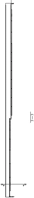
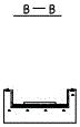
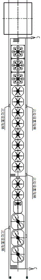
[0027] A mold casting pit design method for a vehicle-mounted mold casting steel pouring system adopts the design concept of a vehicle mold casting steel pouring pit, and arranges two mold casting steel pouring pit production lines A and B, and the two mold casting steel pouring pit production lines are respectively located in two In different spans, each die-casting steel pit is paved with a mold-casting steel-casting vehicle running track, which is convenient for the mold-casting steel-casting vehicle to pour steel. A layer of refractory bricks is laid on the inner wall and bottom of the mold-casting pit. The refractory material drying room for casting is arranged between the lines; figure 1 , 2 As shown in , 3, 4, 5 and 6, the rail gauge of the mold casting pit is designed to be 5500mm, and the inner width of the pit is designed to be 4600mm. 115mm thick refractory bricks. Pad 110mm thick sand at the bottom of the casting pit. The track model is QU120.

[0028] like i...


PUM

PropertyMeasurementUnit
thicknessaaaaaaaaaa

Abstract

The invention relates to the field of metallurgy and specifically relates to a die casting pit design of a vehicle-mounted die casting steel pouring system. The die casting pit design comprises the following steps: arranging A and B two die casting steel pouring pit production lines, wherein the two die casting steel pouring pit production lines are arranged in two different spans respectively, the bottom portion and the inner walls of each die casting pit are respectively paved with a layer of refractory bricks, and a refractory drying room for casting is arranged between the two die casting lines; according to the height of different ingot types of steel ingot dies and use ratio in production, designing the A span to be a two-stage die casting pit, and designing the B span to be a three-stage die casting pit; and putting one-position, two-position, six-position and eight-position four kinds of chassis in the die casting pits according to the corresponding ingot types. According to the design, die casting steel pouring vehicle lift stroke, height change of different ingot types of ingot dies, production power demand information and chassis change characteristics are taken into full consideration, a step-type die casting pit design is adopted, and thus demand for different ingot types and different product die casting production is met by adopting die casting pits with different depths, adjusting the number of central casting pipe bases and improving steel ladle height.

Description

technical field [0001] The invention relates to the field of metallurgy, in particular to a method for designing a mold casting pit of a vehicle-mounted mold casting steel pouring system. Background technique [0002] Die casting is one of the commonly used casting methods for special steel production. It is characterized by low investment and flexible production, and is suitable for the production of small batches and large ingots. The traditional die-casting line design adopts the following methods: (1) The metallurgical crane is used as the main carrier for lifting and casting, the die-casting line is directly designed on the ground of the factory building and the chassis and mold are arranged, and a steel structure casting is set up on one side Operating platform, on which the operator performs steel pouring operations, which can cast different ingot shapes and has strong adaptability; (2) Dig a mold casting pit with the same depth in the workshop, swing the mold in the ...

Claims


Application Information

Patent Timeline
Patent Type & Authority Patents(China)
IPC IPC(8): B22D35/02B22D47/00
Inventor 祁跃峰郭孟朝商长明仇鹏飞李荣昌
Owner HENAN ZHONGYUAN SPECIAL STEEL EQUIP MFG CO LTD
Why Eureka
Try Eureka