
Pipe end hoop welding and fixing device for automobile pipe

A technology for fixing devices and pipe fittings, which is applied in the direction of auxiliary devices, welding equipment, auxiliary welding equipment, etc., can solve the problems affecting the axial processing accuracy, the deformation of automobile pipe fitting clamps, and the circumferential offset, so as to achieve reliable work, positioning and Good stability and simple operation

Active Publication Date: 2015-08-12
ZIXING YUEXING AUTO PARTS MFG
View PDF6 Cites 43 Cited by
  • Summary
  • Abstract
  • Description
  • Claims
  • Application Information

AI Technical Summary

Problems solved by technology

[0002] At present, when the pipe ends of automobile pipe fittings are welded with the clamps, it is necessary to fix the position of the automobile pipe fittings and clamps. Now, mechanical clamps are generally used for positioning, because the automobile pipe fittings are hollow casings with large diameters, and mechanical clamps are used. When positioning, if the force of the clamp is strong, it is easy to deform and dent the clamp of the automobile pipe fitting. If the force of the clamp is light, the relative position between the pipe end of the automobile pipe fitting and the clamp is easy to shift, and the clamp and the pipe end of the automobile pipe fitting are accurate. The welding forming position is that the pipe end of the automobile pipe fittings should exceed the clamp by 0.5mm, and the precision requirement is high. If the mechanical clamp positioning method is used, if the force is light, it will affect the axial processing accuracy, and due to the action of the electrode during the welding process, it will also cause peripheral Offset

Method used


Image

  • Pipe end hoop welding and fixing device for automobile pipe
  • Pipe end hoop welding and fixing device for automobile pipe

Examples


Embodiment Construction

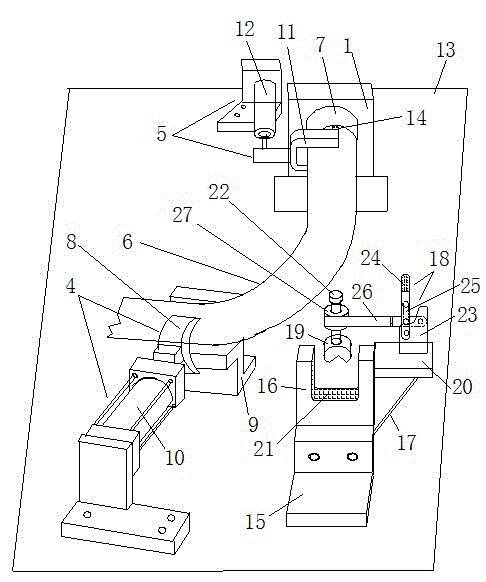
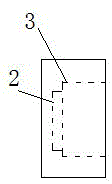
[0016] refer to figure 1 , figure 2 , propose an embodiment of the present invention, and this embodiment comprises workbench and the tube head positioning plate 1 that is fixed on the workbench, fixture, and the tube head positioning plate is provided with automobile pipe fitting limit groove 2, clip limit Groove 3, the fixture includes a side push pipe fixture 4 that presses the automobile pipe fitting 6 into the automobile pipe fitting limit groove 2, and compresses the clamp 7 that is set outside the automobile pipe fitting into the clamp limit groove 3 The hoop fixture 5 is a hoop pipe fixture 15 for clamping and positioning the automobile pipe fittings, and the positions of the three fixtures are adjustable. The working surface of the pipe fitting jaw 8 is arc-shaped, which is suitable for the shape of the automobile pipe fitting it clamps; the supporting plate is provided with an L-shaped bracket. The hoop pipe fixture 15 includes a hoop base, a bracket 16, a brack...


PUM


Abstract

The invention discloses a pipe end hoop welding and fixing device for an automobile pipe, and belongs to the field of automobile pipe end machining equipment. The device comprises a worktable, a pipe head positioning plate and clamps, wherein the pipe head positioning plate and the clamps are fixed to the worktable. The pipe head positioning plate is provided with a pipe limiting groove and a hoop limiting groove. The clamps comprise a hoop clamp, a lateral pushing pipe clamp and an annular hoop pipe clamp, wherein the hoop clamp can press a hoop arranged outside the automobile pipe in a sleeving mode to the interior of the hoop limiting groove; the lateral pushing pipe clamp is used for pushing the automobile pipe to the interior of the automobile pipe limiting groove to be pressed; the annular hoop clamp is used for clamping and positioning the automobile pipe. The positions of the three clamps are adjustable. The automobile pipe limiting groove and the hoop limiting groove form a step type annular groove. By means of the pipe end hoop welding and fixing device, the pipe end of the automobile pipe and the hoop can be precisely positioned, the pipe end and the hoop can not deviate in the machining process, clamping marks can not be generated on the automobile pipe, and the automobile pipe can not be damaged.

Description

technical field [0001] The invention relates to a processing equipment for pipe ends of automobile pipe fittings, in particular to a clamp welding and fixing device for pipe ends of automobile pipe fittings. Background technique [0002] At present, when the pipe ends of automobile pipe fittings are welded with the clamps, it is necessary to fix the position of the automobile pipe fittings and clamps. Now, mechanical clamps are generally used for positioning, because the automobile pipe fittings are hollow casings with large diameters, and mechanical clamps are used. When positioning, if the force of the clamp is strong, it is easy to deform and dent the clamp of the automobile pipe fitting. If the force of the clamp is light, the relative position between the pipe end of the automobile pipe fitting and the clamp is easy to shift, and the clamp and the pipe end of the automobile pipe fitting are accurate. The welding forming position is that the pipe end of the automobile p...

Claims


Application Information

Patent Timeline
Patent Type & Authority Applications(China)
IPC IPC(8): B23K37/053B23K37/04B23K101/06B23K101/30
CPCB23K37/0461B23K37/0533B23K2101/06B23K2101/30
Inventor 陈诚黄海
Owner ZIXING YUEXING AUTO PARTS MFG
Learn More