Rotating pump

A rotary pump and rotary axis technology, applied in the direction of rotary piston pumps, pumps, rotary piston machines, etc., can solve problems such as difficult to achieve discharge, difficult to ensure the durability of the sealing mechanism, etc.

Inactive Publication Date: 2015-08-12
ADVICS CO LTD
View PDF6 Cites 0 Cited by
  • Summary
  • Abstract
  • Description
  • Claims
  • Application Information

AI Technical Summary

Problems solved by technology

Thus, it is difficult to secure the durability of the sealing mechanism and realize the discharge of high-pressure brake fluid

Method used


Image

  • Rotating pump
  • Rotating pump
  • Rotating pump

Examples


no. 1 approach

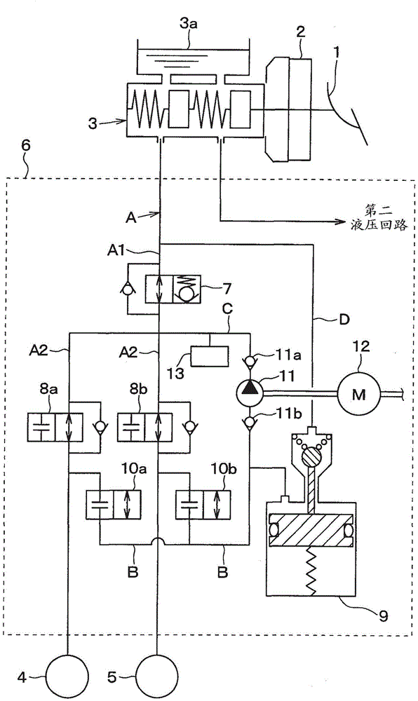
[0030] refer to figure 1 , shows an automotive braking system equipped with a rotary pump that is part of the hydraulic circuit of the braking system. The braking system referred to herein is designed as a so-called diagonal distribution system comprising two brake hydraulic circuits, one of which controls the right front wheel and the left rear wheel, Another brake hydraulic circuit controls the left front and right rear wheels, but the brake system can also be designed as a front / rear split system.

[0031] The braking system is equipped with a brake pedal 1 (that is, a brake actuating member), a brake booster 2, a master cylinder 3, a wheel cylinder 4, a wheel cylinder 5, and a brake pressure control actuator 6, the brake pedal 1 Depressed by a vehicle occupant or driver to apply the brakes to the vehicle. A master cylinder 3 , which will be described in detail later, is used to generate brake hydraulic pressure in response to the operation of a brake actuating member, ie...


PUM


Abstract

A rotating pump includes an outer and an inner rotor disposed in a casing with a gap between the casing and the outer rotor. The rotating pump also includes a first and a second sealing member in the casing to define a low-pressure region and a high-pressure region within the gap. Each of the first and second sealing members is made up of a seal functioning portion and an elastically pressing portion. The seal functioning portion includes a resinous member and a deformation-suppressing member. The resinous member contacts the outer rotor and a low-pressure side inner surface of the casing to establish a difference in pressure between the low-pressure region and the high-pressure region. The deformation-suppressing member works to stop the resinous member from deforming undesirably. This minimizes the risk of breakage of the resinous member and enables the rotating pump to discharge the fluid at an increased pressure.

Description

technical field [0001] The present disclosure generally relates to a rotary pump designed to suck in fluid and then discharge it, and more particularly to a rotary pump that is useful for sucking and discharging brake fluid to condition the brake fluid. Braking systems that control the pressure and thus the braking force are useful. Background technique [0002] Japanese Patent First Publication No. 2002-295376 teaches using an internal gear pump such as a trochoid pump as a rotary pump for a brake system of an automobile. This type of rotary pump consists of an inner rotor, an outer rotor and a casing. The inner rotor is equipped with outer teeth formed on its outer periphery. The outer rotor is equipped with inner teeth formed on its inner periphery. The outer rotor and the inner rotor are installed in the housing. Specifically, within the housing, the teeth of the inner rotor mesh with the teeth of the outer rotor to define a plurality of cavities (ie, voids). If a l...

Claims


Application Information

Patent Timeline
Patent Type & Authority Applications(China)
IPC IPC(8): B60T17/00F16J15/16
CPCF04C2/14F04C15/06F04C15/0015F01C19/005F04C2/102F04C15/0034
Inventor 久田庆武渕田刚
Owner ADVICS CO LTD
Why Eureka
Try Eureka