Adjustable turbulent flow system

An adjustable, airflow channel technology, applied in the direction of streamlined body, aerodynamic improvement, body and other directions, can solve the problems of car breakthrough, slippage, difficult to alleviate, etc., to improve acceleration and top speed performance, restrain body roll, reduce Effects of wind resistance and downforce

Inactive Publication Date: 2015-08-12
王铁苗
View PDF10 Cites 5 Cited by
  • Summary
  • Abstract
  • Description
  • Claims
  • Application Information

AI Technical Summary

Problems solved by technology

[0003] In the actual driving process, especially in the case of high-speed curves, the car will have a tendency to roll to the outside of the curve due to the centrifugal effect, and the positive pressure on the tires located on the inside of the curve is reduced, while the tires on the outside of the curve The positive pressure on the tires increases, and the car has a large roll, which will easily cause the car to break through the adhesion limit of the outer wheel of the curve and slip.
However, since the front and rear wings exert the same downforce on the left and right sides of the car, it is still difficult to alleviate this situation

Method used


Image

  • Adjustable turbulent flow system
  • Adjustable turbulent flow system
  • Adjustable turbulent flow system

Examples


Embodiment Construction

[0027] The present invention will be further described below in conjunction with the accompanying drawings and specific embodiments.

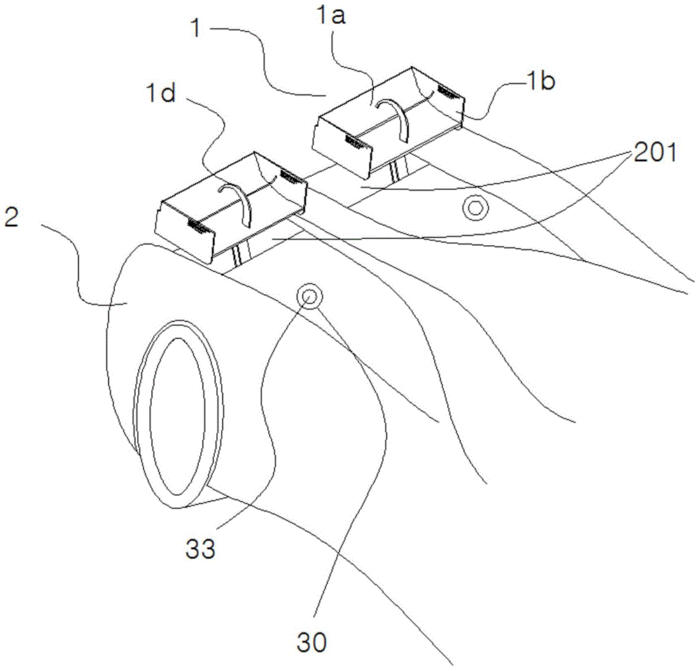
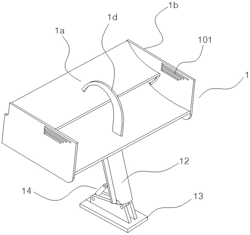
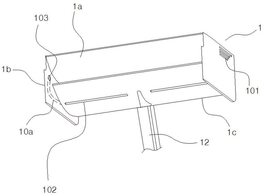
[0028] Such as Figure 1 to Figure 9In the shown embodiment, an adjustable spoiler system includes two empennage structures 1, an air flow channel 201 and hydraulic pipelines, wherein the empennage structure is arranged at the rear of the car 2, and the two empennage structures are along the The central axis of the car is arranged symmetrically. The airflow channel is located at the rear of the car, with openings facing upwards, one on each side, corresponding to the rear wing structure, and the airflow flowing through the upper part of the vehicle body will flow to the rear of the car along the airflow channel. The empennage structure is located at the end of the airflow channel, including the main wing 1c, the aileron 1a and the drive mechanism. The main wing and the aileron are arranged in parallel, the main wing is located below the ailero...


PUM


Abstract

The invention discloses an adjustable turbulent flow system which comprises two spoiler structures, airflow channels and a hydraulic pipeline. The spoiler structures are located at the tail ends of the airflow channels and comprises main wings, auxiliary wings and drive mechanisms, the main wings are located below the auxiliary wings, the front ends of the auxiliary wings are close to the tail ends of the main wings, end boards are arranged at the same side ends of the main wings and the auxiliary wings, the main wings and the end boards are fixedly connected, the auxiliary wings and the end boards are rotationally connected, rotary boards arranged parallel to the end boards are arranged at the middle portions of the main wings, the other ends of the rotary boards are hinged to the auxiliary wings, the drive mechanisms comprises auxiliary wing cylinders and bases, and rotary auxiliary cylinders are arranged on the bases. The hydraulic pipeline comprises a hydraulic pump, an auxiliary pipeline and a rotary auxiliary pipeline. Multiple strip-shaped through holes formed in parallel are formed in the positions above the auxiliary wings, of the front sides of the end boards. By the adoption of the adjustable turbulent flow system, the pressing force and the air resistance of the left side and the right side of the tail portion of an automobile can be adjusted, so that the attaching performance of the automobile is improved, and the tire load is reduced.

Description

technical field [0001] The invention belongs to the field of automobiles, and in particular relates to an adjustable spoiler system. Background technique [0002] During the driving process of the car, due to the shape and structure characteristics of the car itself, the car will generate an upward lift when driving, and the adhesion between the car and the ground will decrease. When the car is running at a high speed, this phenomenon is more prominent. In order to alleviate the negative impact of lift on the driving stability of the car as much as possible, designers often start from the shape of the car and optimize the shape of the car to reduce the lift generated. In addition, on high-performance cars, sports cars or racing cars, in order to improve the adhesion of the car to the ground when cornering, a front wing or tail will be installed on the head or tail of the car. The cross-sectional shape of the wing is similar, but its installation method is just opposite to t...

Claims


Application Information

Patent Timeline
Patent Type & Authority Applications(China)
IPC IPC(8): B62D35/00
CPCY02T10/82
Inventor 王铁苗王楠王铁霞王国良
Owner 王铁苗
Why Eureka
Try Eureka