Auto quenching device and auto quenching method

A kind of quenching equipment and automatic technology, which is applied in the direction of quenching device, heat treatment equipment, furnace, etc., can solve the problems of affecting the mechanical properties of the motor shaft, affecting the straightness of the motor shaft, and the damage of the motor shaft structure, so as to ensure straightness, Avoid damage, avoid the effect of slight bending

Active Publication Date: 2015-08-12
宁波美德威机械科技有限公司
View PDF8 Cites 21 Cited by
  • Summary
  • Abstract
  • Description
  • Claims
  • Application Information

AI Technical Summary

Problems solved by technology

However, in the process of quenching the motor mandrel by this kind of quenching machine, there is a certain distance between the heating and cooling areas. When the heated motor mandrel is transported on the conveyor belt, the heat at both ends of the motor mandrel will be transferred to the motor mandrel. The inside of the shaft causes the inside of the motor shaft to be cooked, causing damage to the internal structure of the motor shaft and affecting the mechanical properties of the motor shaft
In addition, erecting the motor mandrel on the conveyor belt may easily cause slight bending of the motor mandrel, which affects the straightness of the motor mandrel

Method used


Image

  • Auto quenching device and auto quenching method
  • Auto quenching device and auto quenching method
  • Auto quenching device and auto quenching method

Examples


Embodiment Construction

[0060] The present invention will be further described in detail below in conjunction with the accompanying drawings and embodiments.

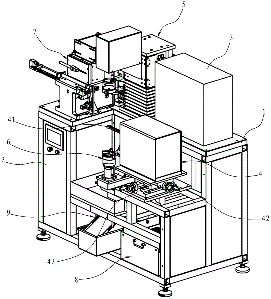
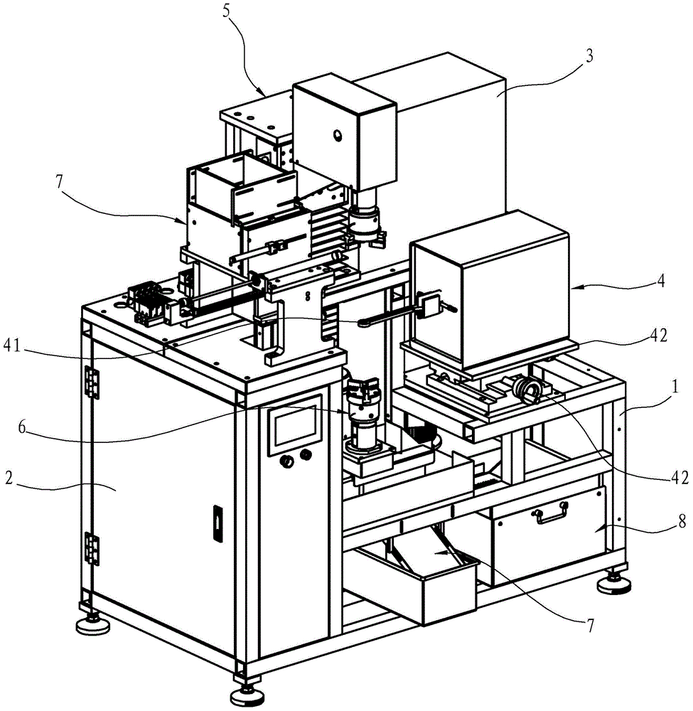
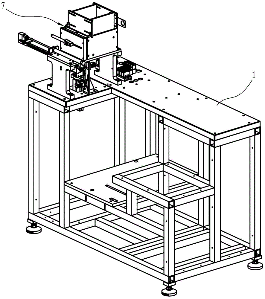
[0061] Such as Figures 1 to 4 As shown, the present invention discloses an automatic quenching equipment, which is used for quenching shaft workpieces, and is especially suitable for quenching the ends of motor mandrels, including a frame 1, and an automatic feeding mechanism 7 arranged on the frame 1, Rotary lifting mechanism, material receiving mechanism 7, reflux cooling mechanism 8, electric control box 2, high frequency machine 3 and induction machine 4, etc. Wherein, the high-frequency machine 3 is used to generate high-frequency current on the induction coil 41; the induction coil 41 connected to the high-frequency power circuit is horizontally arranged on the induction machine 4, and the induction coil 41 is connected with the induction machine 4, and the induction machine 4 Two sliding plates 42 for adjusting the planar position of ...


PUM


Abstract

The invention discloses an auto quenching device which includes a rack and an induction coil connected to a high-frequency power supply circuit. The auto quenching device is characterized by including: a rotary lifting mechanism including a pneumatic gripper which is arranged longitudinally and used for clamping a shaft workpiece and can be rotated with the axial line itself and lifted vertically; an automatic material feeding mechanism arranged beside the rotary lifting mechanism, wherein the automatic material feeding mechanism is used for sending the shaft workpiece into the rotary lifting mechanism from a material arranging box so that the shaft workpiece can be clamped by the pneumatic gripper of the rotary lifting mechanism; a material receiving mechanism arranged under the rotary lifting mechanism and used for receiving a quenched shaft workpiece; and the induction coil which is arranged transversally and is matched with the pneumatic gripper clamping the shaft workpiece in the rotary lifting mechanism, wherein cooling liquid flows through the induction coil. The auto quenching device can achieve an automatic quenching function on the shaft workpiece. The shaft workpiece is cooled by spraying water thereon directly, so that heat is effectively prevented from transferred into the interior of the workpiece. The pneumatic gripper in the rotary lifting mechanism clamps the shaft workpiece longitudinally, thereby ensuring linear degree of the shaft workpiece.

Description

technical field [0001] The invention relates to an automatic quenching device and an automatic quenching method using the device to quench both ends of a shaft workpiece (especially a motor mandrel). Background technique [0002] Quenching refers to a heat treatment method that uses high-frequency current (30K-1000KHZ) to locally heat and cool the surface of the workpiece to obtain a surface hardened layer. This method only strengthens the surface of the workpiece at a certain depth, while the core basically maintains the structure and performance before treatment, so it can obtain a combination of high strength, high wear resistance and high toughness. And because of local heating, it can significantly reduce quenching deformation and reduce energy consumption. [0003] The traditional manual quenching method is that the worker directly holds the workpiece, puts the part of the workpiece that needs to be quenched into the induction coil with high-frequency current, and wai...

Claims


Application Information

Patent Timeline
Patent Type & Authority Applications(China)
IPC IPC(8): C21D1/62C21D9/28
Inventor 陈剑伦
Owner 宁波美德威机械科技有限公司
Why Eureka
Try Eureka