Safety telescopic guardrail
A safe guardrail technology, applied in the direction of road safety devices, roads, roads, etc., can solve the problems of endangering the safety of personnel, the crossbar is detached from the puncture vehicle, and the guardrail cannot be installed and installed, so as to achieve the effect of low guardrail deformation
- Summary
- Abstract
- Description
- Claims
- Application Information
AI Technical Summary
Problems solved by technology
Method used
Image
Examples
Embodiment 1
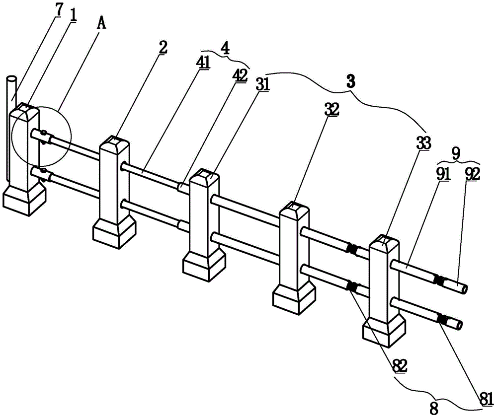
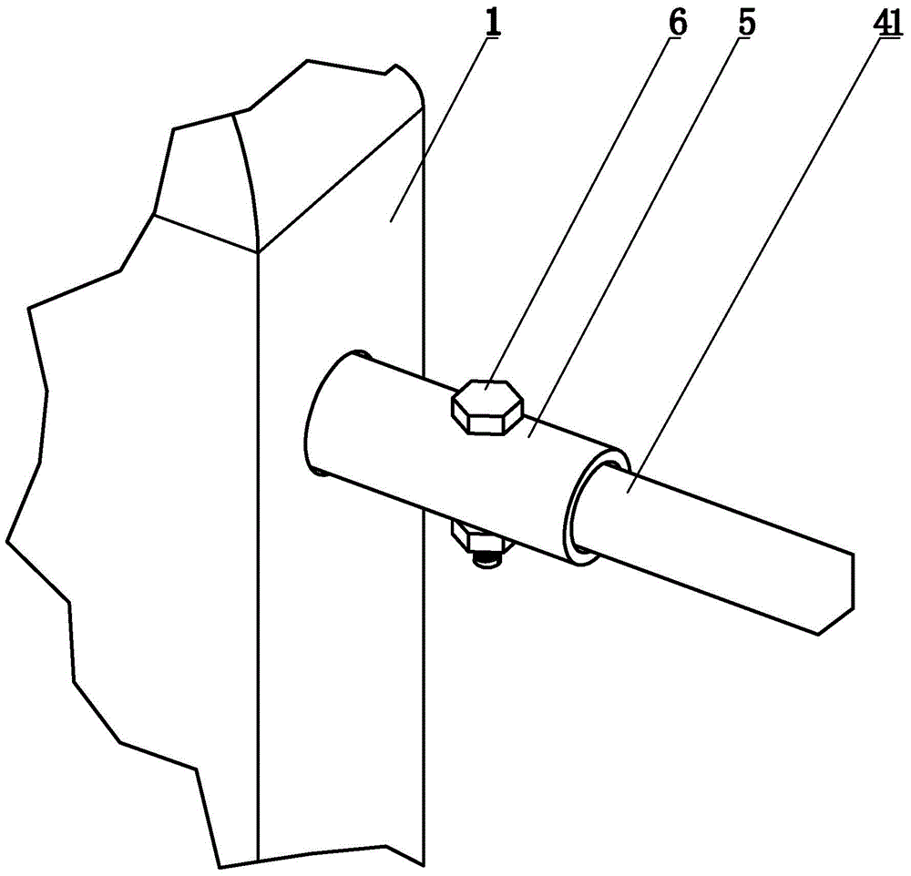
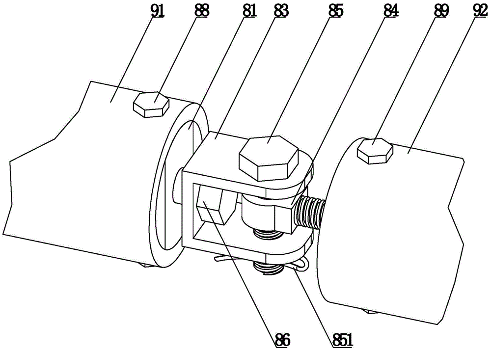
[0033] The telescopic guardrail of this embodiment combines figure 1 , figure 2 with image 3 , Including end isolation pier 1, first isolation pier 2, several secondary isolation piers 3, telescopic piece 4, connecting piece 8 and cross bar 9. The telescopic piece 4 is connected by the telescopic piece 41 and the telescopic piece 42 that can be displaced. One end of the telescopic piece 41 is connected to the end isolation pier 1, and the other end passes through the first isolation pier 2 to connect to the second extension 42. The second telescopic piece 42 passes through the secondary isolation pier adjacent to the first isolation pier 2. One 31; the secondary isolation pier one 31, the secondary isolation pier two 32 and the secondary isolation pier three 33 are connected by a cross bar 9. The cross bar 9 is composed of a cross bar 91 and a cross bar 92, and the secondary isolation pier 2 The crossbar 91 and the crossbar 92 between the secondary isolation piers after 32 (be...
Embodiment 2
[0037] The configuration and working principle of this embodiment are the same as that of the first embodiment. The difference is that: the first telescopic piece 41 and the second telescopic piece 42 are tubular structures, and the pipe diameter of the first telescopic piece 41 is larger than the pipe diameter of the second telescopic piece 42. The two 42 are sleeved in the first telescopic element 41, and the first telescopic element 41 can slide along the outer wall of the second telescopic element 42, so as to realize the relative displacement movement of the first telescopic element 41 and the second telescopic element 42.
Embodiment 3
[0039] The configuration and working principle of this embodiment are the same as that of the first embodiment. The difference is that: the first telescopic piece 41 and the second telescopic piece 42 are tubular structures, and the pipe diameter of the first telescopic piece 41 is larger than the pipe diameter of the second telescopic piece 42. The second 42 is sleeved in the first telescopic piece 41, and the first telescopic piece 41 can slide along the outer wall of the second telescopic piece 42, so as to realize the relative displacement movement of the first telescopic piece 41 and the second telescopic piece 42; at the outer side of the end isolation pier 1. A warning device 7 is provided. The warning device is installed on the end isolation pier 1 in a tubular structure. At night or in the case of poor light, it serves as a warning reminder for vehicles approaching in the distance, so as to prevent the driver from being distracted. The collision caused by clearing the e...
PUM
 Abstract
Description
Claims
Application Information
 - R&D
- Intellectual Property
- Life Sciences
- Materials
- Tech Scout
- Unparalleled Data Quality
- Higher Quality Content
- 60% Fewer Hallucinations
Browse by: Latest US Patents, China's latest patents, Technical Efficacy Thesaurus, Application Domain, Technology Topic, Popular Technical Reports.
© 2025 PatSnap. All rights reserved.Legal|Privacy policy|Modern Slavery Act Transparency Statement|Sitemap|About US| Contact US: help@patsnap.com


