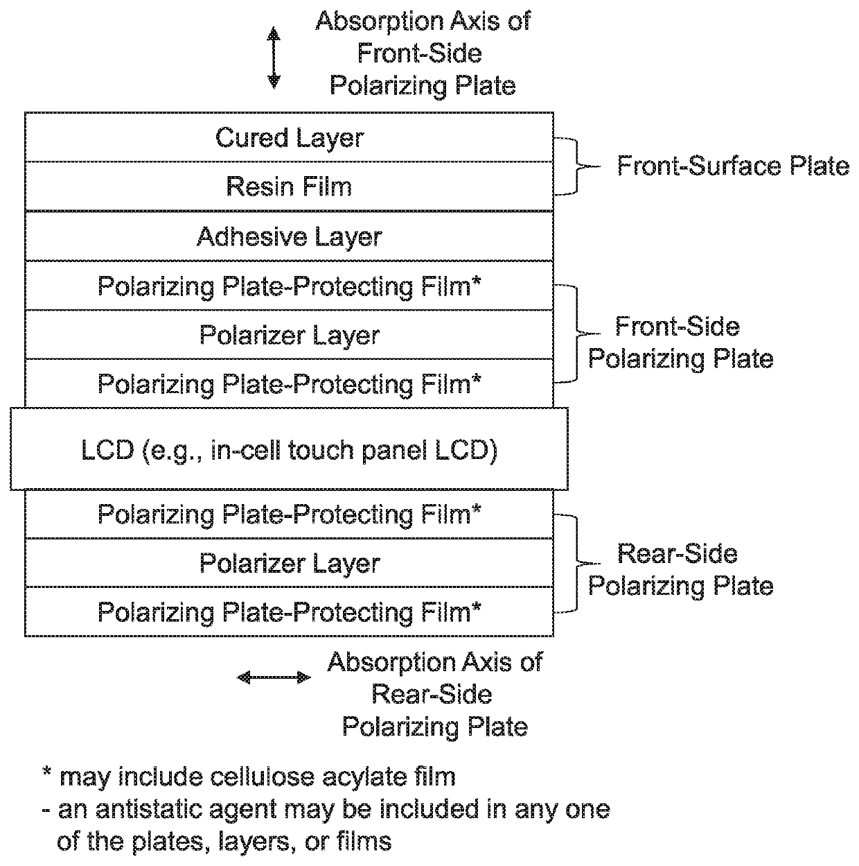
[0006]Meanwhile, JP2014-89270A discloses that bonding the polarizer layer with the optical laminate is performed by exploiting a water adhesion action of a polyvinyl alcohol (PVA)-based polarizing film without intervention of another adhesive layer (see paragraphs 0037 and 0051 in JP2014-89270A). Meanwhile, a polarizing plate which is currently widely used is configured such that a polarizer layer is positioned between two polarizing plate-protecting films as described above. In a case of bonding such a polarizing plate with a front-surface plate, the surface of the polarizing plate, with which the front-surface plate is bonded, becomes the surface of the polarizing plate-protecting film (specifically, the outer protective film of the front-side polarizing plate). Accordingly, in this case, it is considered that the front-surface plate is bonded with the front-side polarizing plate via an adhesive layer. Further, also in a case where the polarizer layer is directly bonded with the front-surface plate, it is considered to use an adhesive layer from the viewpoint of enhancing the adhesiveness between the polarizer layer and the front-surface plate.
[0008]Therefore, the present invention has an object to provide a liquid crystal panel including a polarizing plate formed by bonding a front-surface plate including at least a resin film with a front-side polarizing plate via an adhesive layer, in which occurrence of display unevenness in a high-humidity environment is reduced in a case where the liquid crystal panel is assembled into a liquid crystal display device.
[0018]In the liquid crystal panel, the respective constitutive members as described above are in an integrally laminated state. In a liquid crystal panel in which the respective constitutive members are in an integrally laminated state, in a case where a given constitutive member absorbs moisture in a high-humidity environment to cause deformation (humidity dimensional change), the deformation gives an effect on another constitutive member. As a result, the entire liquid crystal panel can be deformed. For a front-surface plate including a glass widely used in the related, it is considered that since a glass has a low moisture permeability and a small humidity dimensional change, as compared with a resin film, the degrees of deformation of the front-surface plate and the other constitutive members in a high-humidity environment are small. In contrast, it is presumed that a liquid crystal panel having a front-surface plate including a resin film has a larger deformation of the front-surface plate itself, and a large deformation of the other constitutive members, generated by the effect of moisture penetrated into the front-surface plate than those of a liquid crystal panel having a front-surface plate including a glass in a high-humidity environment.
[0021]The present inventors have thought that the deformation direction (whether the liquid crystal panel is deformed to be in a convex shape on the viewing side or deformed to be in a convex shape on the backlight unit side) and the strength (to what extent the liquid crystal panel is deformed) of the liquid crystal panel having a front-surface plate, a front-side polarizing plate, a liquid crystal display element, and a rear-side polarizing plate in an integrally laminated state in a high-humidity environment usually varies depending on a balance of stress between the front-surface plate and the front-side polarizing plate (hereinafter also collectively referred to as a “viewing-side member”) positioned on the viewing side of the liquid crystal display element, and the rear-side polarizing plate. Further, the present inventors have presumed that the stress of the respective constitutive members in a high-humidity environment can be indicated by “Modulus of elasticity×Thickness×Humidity dimensional change rate which will be described later” of the respective constitutive members as an index. Here, the present inventors have thought that the stress of the viewing-side member is also changed by an extent that an adhesive layer positioned between the front-surface plate and the front-side polarizing plate transfers the stress of the front-surface plate to the front-side polarizing plate which is integrally laminated therewith, the stress relaxation rate of the adhesive layer, details of which will be described later can be used as an indicator. Further, the present inventors have presumed that in order to make the adhesive layer play a role in controlling the deformation of the entire liquid crystal panel, the thickness should be 2 μm or more. Incidentally, the present inventors have presumed that taking into account the stress relaxation rate of the adhesive layer, a difference between “ECp×dCp×εCp×(100−P) / 100+(Ef×df×εf)” for the viewing-side member of Formula A-1 as described above and “(Er×dr×εr)” for the rear-side polarizing plate can be indicative of a balance of stress between the viewing-side member and the rear-side polarizing plate in a high-humidity environment, and by making the difference satisfy Formula A-1, the entire liquid crystal panel can be deformed to be in a convex shape on the viewing side to an extent that occurrence of annular unevenness can be suppressed in a high-humidity environment, and thus, occurrence of circular unevenness can be suppressed.
[0041]Moreover, in an aspect in which the front-surface plate includes the “easily adhesive layer” which will be described later, the easily adhesive layer becomes the outermost layer on the adhesive layer side of the front-surface plate, and its surface becomes the surface bonded with the adhesive layer. The easily adhesive layer can play a role in improving the adhesion force between the front-surface plate and the adhesive layer, and encompasses an easily adhesive layer caused by a pressure-sensitive adhesive and an easily adhesive layer caused by an adhesive. The pressure-sensitive adhesive and the adhesive are as set forth above.

