Camshaft bearing structure

a technology of camshaft and bearing, which is applied in the direction of valve arrangement, cylinder, machine/engine, etc., can solve the problems of hotness of the cylinder head, and achieve the effect of small deformation degree, small large degree of thermal deformation

Inactive Publication Date: 2015-12-31
TOYOTA JIDOSHA KK
View PDF4 Cites 2 Cited by
  • Summary
  • Abstract
  • Description
  • Claims
  • Application Information

AI Technical Summary

Benefits of technology

[0014]The bearing part for an exhaust camshaft tends to become very hot because of heat from exhaust gas and therefore tends to undergo a large degree of thermal deformation. According to the above configuration, the cam cap is not restrained by a positioning member in the outer part of the bearing part for the exhaust camshaft. Thus, when the cylinder head is deformed such that an upper part thereof gradually rises toward a lateral side of the cylinder head due to heat from exhaust gas, the cylinder head is displaced relative to the cam cap in the outer part. Thus, compared to the case where the cam cap is restrained by positioning members, the semi-circular arch-shaped portion of the cam cap that surrounds the journal hole undergoes a smaller degree of deformation and the resulting deformation of the journal hole will be smaller. As a result, deformation of the cylinder head does not lead to significant deformation of the journal hole.

Problems solved by technology

In particular, in the vicinity of the exhaust camshaft, the cylinder head tends to become very hot because of heat from the exhaust gas and therefore undergoes a large degree of thermal deformation.

Method used


Image

  • Camshaft bearing structure
  • Camshaft bearing structure
  • Camshaft bearing structure

Examples


Embodiment Construction

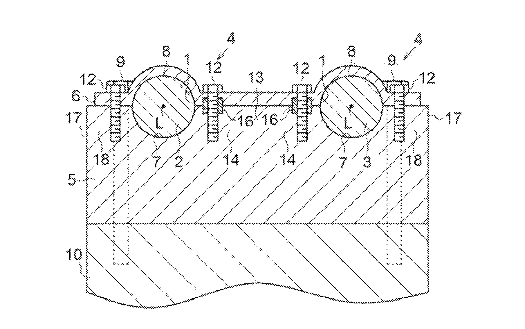
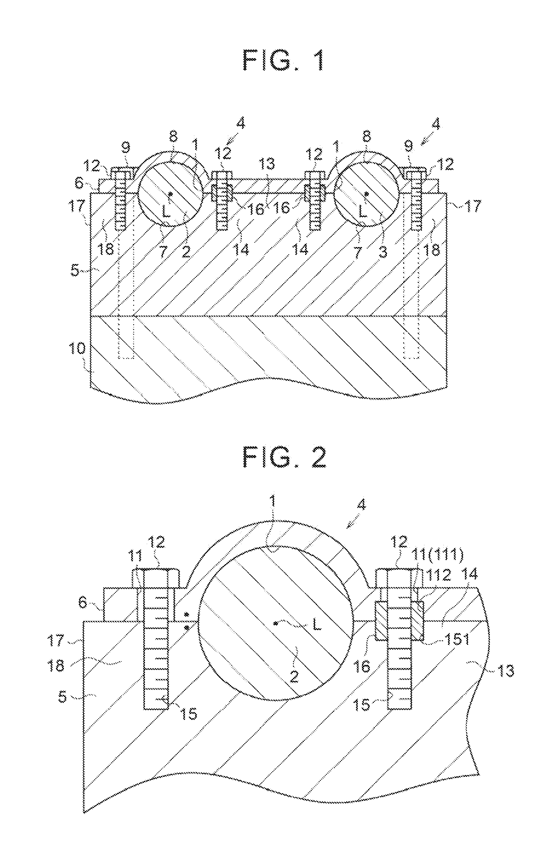
[0021]One embodiment of a camshaft bearing structure is hereinafter described with reference to FIG. 1 to FIG. 5. As shown in FIG. 1, the camshaft bearing structure has bearing parts 4. Each bearing part 4 rotatably supports an exhaust camshaft 2 or intake camshaft 3 that extends through a journal hole 1. Semicircular recesses 7 are provided side by side in an upper surface of a cylinder head 5. A cam cap 6 has semicircular recesses 8 that are defined by semi-circular arch-shaped portions opposed to the recesses 7 and symmetrical in shape to the recesses 7. The cam cap 6 is assembled to an upper surface of the cylinder head 5, so that circular journal holes 1 are formed by the recesses 7 and the recesses 8. In this way, the journal holes 1 of the bearing parts 4 are formed by an upper part of the cylinder head 5 and the cam cap 6, which is assembled to the upper part of the cylinder head 5, The cylinder head 5 is assembled to a cylinder block 10 that is located under the cylinder he...


PUM


Abstract

A bearing structure for a camshaft includes a bearing part that includes a cylinder head, a cam cap, and a positioning member. The cam cap is assembled to an upper part of the cylinder head. The cylinder head and the cam cap define a journal hole. The cylinder head and the cam cap rotatably support the camshaft in the journal hole. The positioning member determines the position where the cylinder head and the cam cap are assembled to each other. The positioning member is press-fitted into the cylinder head and the cam cap. In the bearing part for the camshaft, the positioning member is provided only in an inner part, which is a part of the bearing part between an axis of the camshaft and a center of an upper part of the cylinder head.

Description

INCORPORATION BY REFERENCE[0001]The disclosure of Japanese Patent Application No. 2014-130118 filed on Jun. 25, 2014 including the specification, drawings and abstract is incorporated herein by reference in its entirety.BACKGROUND OF THE INVENTION[0002]1. Field of the Invention[0003]The present invention relates to a camshaft bearing structure that rotatably supports a camshaft.[0004]2. Description of Related Art[0005]Japanese Patent Application Publication No, 2011-241700 (JP 2011-241700 A) discloses one example of a bearing structure for an intake camshaft or exhaust camshaft. As shown in FIG. 4, this bearing structure has a bearing part 102 that rotatably supports a camshaft 101 that extends through a journal hole 100. The journal hole 100 is defined by an upper part of a cylinder head 103 and a cam cap 104 that is assembled to the upper part of the cylinder head 103. The bearing part 102 includes pins 105 that are press-fitted into both the upper part of the cylinder head 103 an...

Claims


Application Information

Patent Timeline
Patent Type & Authority Applications(United States)
IPC IPC(8): F01L1/46F01L1/047F02F1/24
CPCF01L1/46F02F1/24F01L1/047F01L2001/0476
Inventor FUJIWARA, MASAHIRONISHIMURA, YUTA
Owner TOYOTA JIDOSHA KK
Why Eureka
Try Eureka