
A gas drilling cuttings processing system based on cyclone separation

A gas drilling and processing system technology, applied in the field of drilling, can solve the problems of easy accumulation of cuttings, waste of resources, physical injury, etc., and achieve the effects of improving air quality, saving water resources, and convenient transportation

Active Publication Date: 2017-07-11
CHONGQING UNIVERSITY OF SCIENCE AND TECHNOLOGY
View PDF12 Cites 0 Cited by
  • Summary
  • Abstract
  • Description
  • Claims
  • Application Information

AI Technical Summary

Problems solved by technology

At present, the treatment method for rock-carrying gas in the process of gas drilling in China is to simply process the rock-carrying gas returned to the ground in the annulus (spray the gas with a pump) and then discharge it directly or connect the sand discharge pipeline to the combustion pool for ignition , cuttings are easy to accumulate, affecting the subsequent use of the combustion pool
This not only pollutes the environment but also wastes resources. In windless or downwind gas drilling sites, dust is very serious.
Workers working in such an environment for a long time will cause very serious injuries to their bodies. It is urgent to develop new dust removal tools to deal with the cuttings carried in the gas returned from gas drilling.
[0003] In order to solve the above problems, some domestic literatures have proposed the technology of using two-stage cyclone separator to separate the solids and drilling gas in the rock-carrying gas. Under field conditions, the effect simulated in the laboratory cannot be achieved, and the situation of dusty sky still exists

Method used


Image

  • A gas drilling cuttings processing system based on cyclone separation

Examples


Embodiment Construction

[0011] Specific embodiments of the present invention will be described in detail below in conjunction with specific drawings. It should be noted that the technical features or combinations of technical features described in the following embodiments should not be regarded as isolated, and they can be combined with each other to achieve better technical effects.

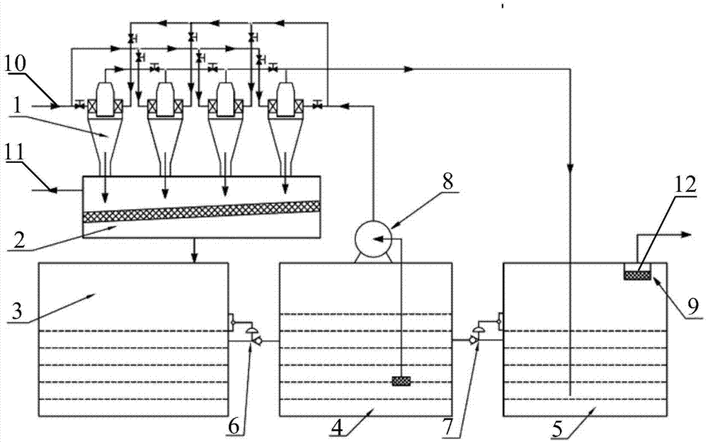
[0012] Such as figure 1 As shown, the present invention provides a gas drilling cuttings processing system based on cyclone separation, including: cyclone separator 1, cleaner 2, first water tank 3, second water tank 4, third water tank 5, centrifugal pump 8 and anti-overflow exhaust pipe 9; several identical cyclone separators 1 are connected in parallel to form a cyclone separator group, and each cyclone separator 1 is provided with an air inlet 10 for importing drilling gas; cyclone separator 1 There is also a feed port, which is connected to the outlet of the centrifugal pump 8 through a pipeline with a valve; th...


PUM


Abstract

The invention discloses a gas drilling rock debris treatment system based on cyclone separation. The gas drilling rock debris treatment system comprises multiple cyclone separators, a cleaner, a first water tank, a second water tank, a third water tank, a centrifugal pump, a control valve and an anti-overflow exhaust pipe. The identical cyclone separators are connected in parallel to form a cyclone separator set, the cyclone separators are connected with the output end of the centrifugal pump and the third water tank, the cleaner is connected under the cyclone separators, the anti-overflow exhaust pipe is arranged at the top of the third water tank, the third water tank is connected with the second water tank, a water inlet of the centrifugal pump is connected with a water outlet of the second water tank, the second water tank is connected with the first water tank, and the cleaner is connected with the top of the first water tank. The gas drilling rock debris treatment system achieves recycling of water resources and is very practical for some well sites far away from water sources. By means of the gas drilling rock debris treatment system, rock debris in drilling gas can be effectively separated, the air quality of well sites in gas drilling can be greatly improved, water sources can be saved, and meanwhile high-cost gas drilling media can be recycled.

Description

technical field [0001] The invention belongs to the technical field of drilling, and in particular relates to a gas drilling cuttings processing system based on cyclone separation. Background technique [0002] With the development of petroleum engineering drilling technology and drilling technology, gas drilling technology has been gradually used in actual drilling engineering and has shown its unique advantages. Since air (or other gas) is used as "drilling fluid", the treatment of returning "drilling fluid" is quite different from that of conventional liquid drilling fluid. At present, the treatment method for rock-carrying gas in the process of gas drilling in China is to simply process the rock-carrying gas returned to the ground in the annulus (spray the gas with a pump) and then discharge it directly or connect the sand discharge pipeline to the combustion pool for ignition , cuttings are easy to accumulate, affecting the subsequent use of the combustion pool. This ...

Claims


Application Information

Patent Timeline
Patent Type & Authority Patents(China)
IPC IPC(8): E21B21/06
CPCE21B21/07
Inventor 任连城苟鑫华蒋德平董超群
Owner CHONGQING UNIVERSITY OF SCIENCE AND TECHNOLOGY
Learn More