
Panorama holder

A technology of pan-tilt and base, which is applied in the direction of machine platform/support, supporting machine, mechanical equipment, etc., can solve the problems of complex structure, inconvenient operation, and many parts, and achieve the purpose of increasing the selection range, reducing the height, and operating easy effect

Inactive Publication Date: 2015-08-12
广东徕图影像科技有限公司
View PDF7 Cites 3 Cited by
  • Summary
  • Abstract
  • Description
  • Claims
  • Application Information

AI Technical Summary

Problems solved by technology

In order to realize multiple rotation angle options, the general panorama head is provided with positioning holes for multiple gears on the side wall of the pan / tilt, but this increases the height of the panorama pan / tilt, which is not easy to operate and carry
In view of the above problems, in the prior art, positioning holes with multiple gear positions are also arranged on the top wall of the cloud platform, such as the invention patent of China Patent Authorization Announcement No. CN202904194U, which discloses a panoramic view of a rotating base with pinball positioning The photography head includes an upper turntable and a lower turntable. The lower turntable has several concave arcs on different circumference diameters, and the upper turntable is equipped with positioning marbles that match the concave arcs on different circumference diameters. The rotation angle needs to install positioning marbles on the corresponding circumference diameter. This structure reduces the overall height of the head, but the structure is complicated, there are many parts, and the operation is inconvenient. Every time the rotation angle is changed, it needs to be installed on different circumference diameters. positioning marbles

Method used


Image

  • Panorama holder
  • Panorama holder
  • Panorama holder

Examples


Embodiment Construction

[0022] The following will clearly and completely describe the technical solutions in the embodiments of the present invention with reference to the accompanying drawings in the embodiments of the present invention. Obviously, the described embodiments are only some of the embodiments of the present invention, not all of them. Based on the embodiments of the present invention, all other embodiments obtained by persons of ordinary skill in the art without making creative efforts belong to the protection scope of the present invention.

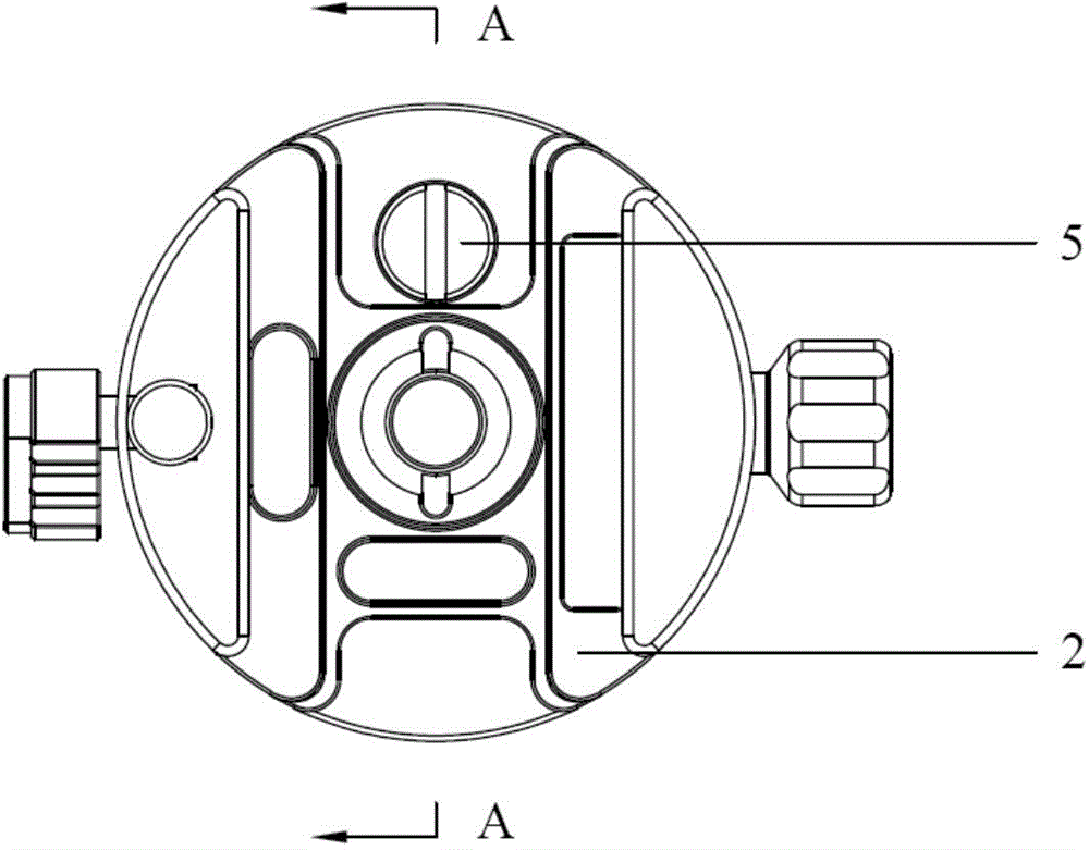
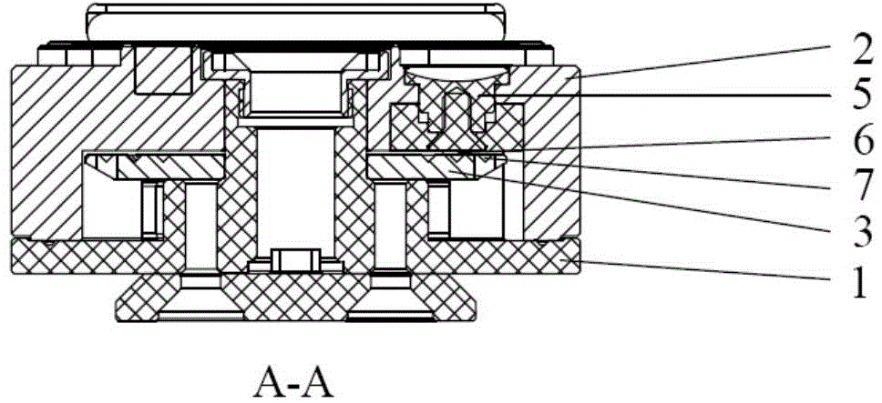
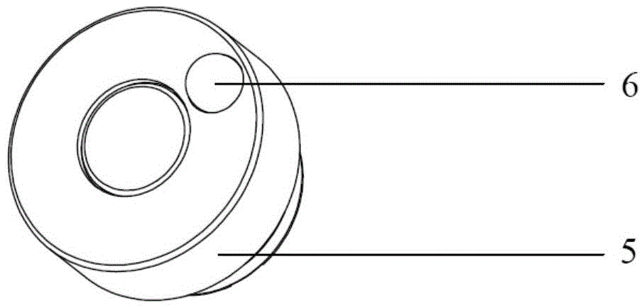
[0023] Such as Figure 1 to Figure 4 A panoramic cloud platform of the present invention is shown, including a base body 1, an indexing plate 3 arranged on the base body 1, a cover body 2 covered on the base body 1, and a relative rotation between the cover body 2 and the base body 1 The positioning mechanism of the position, the positioning mechanism includes a number of positioning holes 4 that are evenly distributed on the surface of the index...


PUM


Abstract

The invention provides a panorama holder comprising a base body, an index dial which is arranged on the base body and a cover body which covers the base body. The panorama holder also comprises a positioning mechanism which adjusts the relative rotating position of the cover body and the base body. The positioning mechanism comprises multiple circles of positioning holes which are circumferentially and evenly distributed on the dial surface of the index dial and positioning knobs which penetrate through the cover body to be contacted with the index dial. The external end parts of the bottom end surfaces of the positioning knobs are provided with positioning marbles which can respectively move into different circles of positioning holes along with rotation of the positioning knobs. The external end parts of the positioning marbles slidably move on the dial surface of the index dial or are clamped in the positioning holes. The panorama holder is simple in structure, convenient to operate and multiple in optional rotating angles. Besides, product height is reduced, carrying is more convenient, scale values do not need to be observed in photographing and thus photographing efficiency is enhanced.

Description

technical field [0001] The invention relates to a supporting device for installing and fixing a video camera, in particular to a multi-level adjustable panorama platform. Background technique [0002] Panoramic photography is to use the camera to shoot the surrounding 360-degree space scenery through the rotation of the panoramic head. In order to meet different photography needs, it is required that the pause angle of a single rotation of the camera is also different. In order to realize the selection of multiple rotation angles, a general panoramic pan / tilt is provided with multiple positioning holes on the side wall of the pan / tilt, but this increases the height of the panoramic pan / tilt, which is not easy to operate and carry. In view of the above problems, in the prior art, positioning holes with multiple gear positions are also arranged on the top wall of the cloud platform, such as the invention patent of Chinese patent authorization announcement number CN202904194U,...

Claims


Application Information

Patent Timeline
IPC IPC(8): F16M11/06F16M11/18
Inventor 邓铜岭
Owner 广东徕图影像科技有限公司
Learn More