
Cold atom interferometer single laser light source system

A light source system and laser technology, applied in lasers, phonon exciters, laser parts and other directions, can solve the problems of immature optical devices in the 780nm band, high influence of atomic interference accuracy, poor frequency locking effect, etc. Mann sideband effect, small frequency modulation range, low cost effect

Active Publication Date: 2021-02-26
NAT UNIV OF DEFENSE TECH
View PDF10 Cites 1 Cited by
  • Summary
  • Abstract
  • Description
  • Claims
  • Application Information

AI Technical Summary

Problems solved by technology

The system only uses a single laser to realize all the light in the process of atomic interference, and uses 1560nm fiber optics, which can improve system integration and reduce system volume. The frequency locking system and laser frequency modulation bandwidth put forward high requirements, and the frequency locking effect is not good
In addition, Wuhan Institute of Physics and Mathematics also proposed a compact single laser system, (Fang Jie, Hu Jiangong, et al. Realization of a compact one-seed laser system for atom interferometer-based gravimeters. [J]. Optics Express, 2018.), The system uses a 780nm laser as a seed source, and also uses a phase modulator to generate sidebands and locks the +1-order sidebands on the atomic transition line, and then generates sidebands through the phase modulator to obtain light of the target frequency, but the 780nm band optical The device is immature, the cost is high, and the degree of integration is low
Moreover, the above laser system schemes all have sideband effects when generating Raman light, which has a high impact on the accuracy of atomic interference

Method used


Image

  • Cold atom interferometer single laser light source system
  • Cold atom interferometer single laser light source system
  • Cold atom interferometer single laser light source system

Examples


Embodiment Construction

[0039] The embodiments of the present invention will be described in detail below with reference to the accompanying drawings, but the present invention can be implemented in various ways defined and covered by the claims.

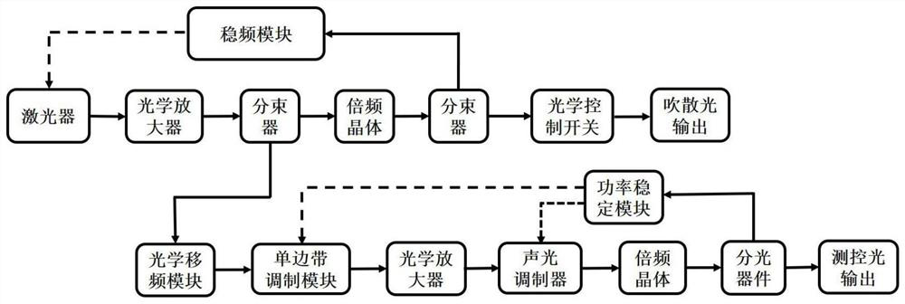
[0040] like figure 1 Described, a kind of cold atom interferometer single laser light source system, described system comprises:

[0041] Reference optical path module and optical frequency shift module;

[0042] The reference optical path module includes a laser and a frequency stabilization module, and the reference optical path module is used to provide a laser source with stable frequency and narrow bandwidth;

[0043] The optical frequency shifting module includes a first electro-optic modulator and a first narrow-bandwidth fiber filter, the first electro-optic modulator and the first narrow-bandwidth fiber filter are connected through an optical fiber; the first electro-optic modulator and The laser fiber is connected;

[0044] The first electro-o...


PUM


Abstract

The invention provides a single-laser light source system of a cold atom interferometer. The single-laser light source system comprises a reference light path module and an optical frequency shift module; the reference light path module comprises a narrow bandwidth laser and a frequency stabilization module; the optical frequency shift module comprises a first electro-optical modulator and a firstnarrow bandwidth optical fiber filter, and the first electro-optical modulator is connected with the first narrow bandwidth optical fiber filter through an optical fiber; the first electro-optical modulator is connected with the laser through an optical fiber; the first electro-optical modulator receives initial light of a laser source, modulates the initial light through a modulation signal of apreset frequency, and generates a sideband of the preset frequency. The first narrow bandwidth optical fiber filter filters the optical signal output by the electro-optical modulator to obtain frequency shift light of a + 1-order sideband; the frequency shift light is used for modulating to obtain measurement and control light of cold atoms related to the instrument. The laser system is low in cost, low in power consumption, movable, small in size and capable of eliminating the Raman sideband effect.

Description

technical field [0001] The invention belongs to the field of quantum precision measurement based on cold atom interference technology, in particular to a cold atom interferometer single laser light source system. Background technique [0002] Atom interferometry uses the characteristics of atomic matter waves as a research method, and is widely used in the field of precision measurement, such as high-precision measurement of physical quantities such as rotational angular velocity, gravitational acceleration, and gravitational constant. In the cold atom interferometer, cold atoms are used as the measurement sensitive medium. Compared with other measurement methods such as optical interference, cold atoms have the advantages of long free evolution time, small atomic group velocity distribution, short de Broglie wavelength and large relative mass. , so that the cold atom interference has better coherence in space and velocity distribution, and thus has higher measurement sensit...

Claims


Application Information

Patent Timeline
IPC IPC(8): H01S3/109H01S3/108H01S3/10
CPCH01S3/109H01S3/1086H01S3/10007H01S3/2391H01S3/0085H01S3/0092H01S3/06758H01S3/1608G01C19/58G01P15/093H01S3/13013G01B9/02015H01S3/06791H01S3/08013H01S3/107H01S3/136H01S3/302
Inventor 杨俊王国超朱凌晓颜树华郭熙业王亚宁吕梦洁徐东洋贾爱爱李期学张旭喻晓
Owner NAT UNIV OF DEFENSE TECH
Learn More