Electrochromic device and color changing method thereof
An electrochromic device and electrochromic technology, applied in the field of color-changing devices, can solve the problems of less electrochromic materials, difficulty in finding cathode electrochromic materials for anode electrochromic materials, and difficulty in switching between colors, etc., to achieve expanded selection range, meet the multi-color display and the effect of personalized customization
- Summary
- Abstract
- Description
- Claims
- Application Information
AI Technical Summary
Problems solved by technology
Method used
Image
Examples
Embodiment 1
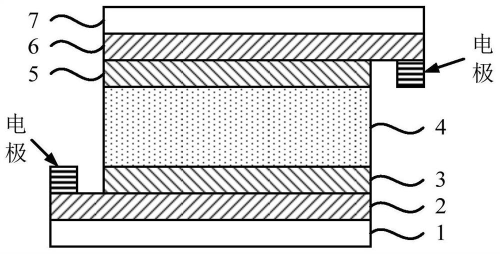
[0114] This embodiment provides an electrochromic device, its structural schematic diagram is as follows figure 1 As shown, it includes a first substrate 1, a first transparent conductive layer 2, a first electrochromic layer 3, an electrolyte layer 4, a second electrochromic layer 5, a second transparent conductive layer 6 and a second substrate 7 stacked in sequence. ; Wherein, the materials of the first electrochromic layer 3 and the second electrochromic layer 5 are all anode electrochromic reduction state coloring materials.
[0115] The preparation method of the electrochromic device is as follows:
[0116] 1) Preparation of the first electrochromic layer 3:
[0117] Dissolve 300mg of poly 2-[(2-ethylhexyloxy)methyl]3,4-thieno-1,4-dioxane in 10mL o-xylene, stir it magnetically for 10h, then drop the obtained solution onto the On the ITO layer (the first transparent conductive layer 2 ) on the glass substrate (the first substrate 1 ), spin-coat and dry to form the first...
Embodiment 2
[0131] This embodiment provides an electrochromic device, its structural schematic diagram is as follows figure 1 As shown, it includes a first substrate 1, a first transparent conductive layer 2, a first electrochromic layer 3, an electrolyte layer 4, a second electrochromic layer 5, a second transparent conductive layer 6 and a second substrate 7 stacked in sequence. ; Wherein, the materials of the first electrochromic layer 3 and the second electrochromic layer 5 are cathode electrochromic oxidation state coloring materials.
[0132] The preparation method of the electrochromic device is as follows:
[0133] 1) Preparation of the first electrochromic layer 3:
[0134] Weigh 80 mg of potassium ferricyanide and dissolve in 25 mL of deionized water, weigh 60 mg of nickel acetate and dissolve in 25 mL of deionized water, and stir evenly. The potassium ferricyanide solution was added to the nickel acetate solution to form a precipitate, and the precipitate was washed three tim...
Embodiment 3
[0148] This embodiment provides an electrochromic device, its structural schematic diagram is as follows figure 1 As shown, it includes a first substrate 1, a first transparent conductive layer 2, a first electrochromic layer 3, an electrolyte layer 4, a second electrochromic layer 5, a second transparent conductive layer 6 and a second substrate 7 stacked in sequence. ; Wherein, the materials of the first electrochromic layer 3 and the second electrochromic layer 5 are cathodic electrochromic reduction state coloring materials.
[0149] The preparation method of the electrochromic device is as follows:
[0150] 1) Preparation of the first electrochromic layer 3:
[0151] Dissolve 100mg, 99.9% pure tungsten powder in 10mL, 30wt% hydrogen peroxide solution, stir at room temperature for 4h, filter off the lower sediment after stirring, add absolute ethanol and glacial acetic acid, and continue stirring for 4h. Then the solution obtained is dropped onto the ITO layer (the first...
PUM
| Property | Measurement | Unit |
|---|---|---|
| Thickness | aaaaa | aaaaa |
| Thickness | aaaaa | aaaaa |
| Thickness | aaaaa | aaaaa |
Abstract
Description
Claims
Application Information
 - R&D
- Intellectual Property
- Life Sciences
- Materials
- Tech Scout
- Unparalleled Data Quality
- Higher Quality Content
- 60% Fewer Hallucinations
Browse by: Latest US Patents, China's latest patents, Technical Efficacy Thesaurus, Application Domain, Technology Topic, Popular Technical Reports.
© 2025 PatSnap. All rights reserved.Legal|Privacy policy|Modern Slavery Act Transparency Statement|Sitemap|About US| Contact US: help@patsnap.com


