Machine tool electric spindle reliability test bench centering adjustment device

A technology of centering adjustment and electric spindle, which is applied in the testing of machine gears/transmission mechanisms, etc., can solve problems such as difficulty in increasing speed, inability to detect misalignment, and exacerbated bearing life, so as to avoid reduction in stiffness and natural frequency and improve versatility And flexibility, the effect of increasing the test speed

Active Publication Date: 2016-08-24
JILIN UNIV
View PDF5 Cites 0 Cited by
  • Summary
  • Abstract
  • Description
  • Claims
  • Application Information

AI Technical Summary

Problems solved by technology

For machine tool high-speed motorized spindle reliability test bench, since the motorized spindle under test rotates at tens of thousands of revolutions per minute, the dynamometer that provides simulated cutting torque for the motorized spindle under test is connected to the motorized spindle under test through a coupling , the misalignment between the dynamometer and the electric spindle under test will not only increase the vibration of the electric spindle under test and the dynamometer, reduce the bearing life and make it difficult to increase the speed, but more importantly, when the electric spindle under test and the dynamometer are out of alignment In the middle, the coupling will generate an additional unpredictable force and moment on the electric spindle under test, so that the loaded force and moment deviate from the set value, causing errors in the reliability test
At present, there are some alignment adjustment devices in China, which can only perform simple adjustments before the test, and cannot detect misalignment during operation and eliminate misalignment in time during operation.

Method used


Image

  • Machine tool electric spindle reliability test bench centering adjustment device
  • Machine tool electric spindle reliability test bench centering adjustment device
  • Machine tool electric spindle reliability test bench centering adjustment device

Examples


Embodiment Construction

[0033] The present invention is described in detail below in conjunction with accompanying drawing:

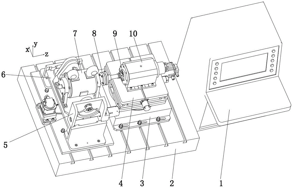
[0034] refer to figure 1 , the centering adjustment device of the machine tool electric spindle reliability test bench, including a horizontal iron 2, a control cabinet 1 and a dynamometer 7 for loading simulated cutting torque on the tested electric spindle 10, the tested electric spindle 10 is a machine tool electric spindle For the high-speed electric spindle to be tested in the reliability test, the input shaft of the dynamometer 7 is coaxially connected with the electric spindle 10 under test through the elastic diaphragm coupling 8, and also includes the rotary table 3, the X-Z table 4, the lift Platform 6 and tilting table 5;

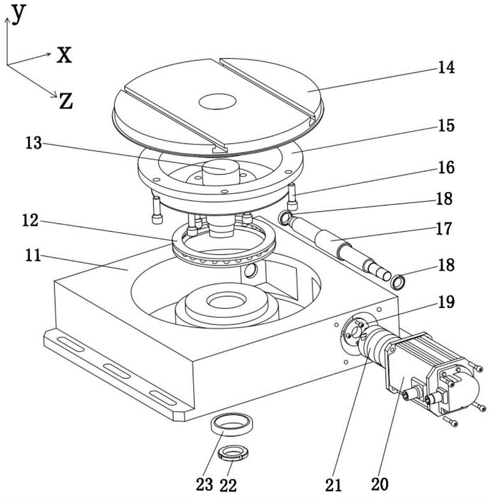
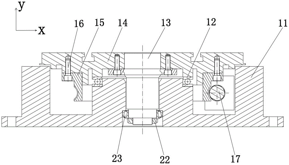
[0035] refer to figure 1 , figure 2 ,and Figure 5 , the two sides of the rotary table base 11 at the bottom of the rotary table 3 are processed with long holes, which are fixed on the right side of the horizontal iron 2 by T-shaped bolts an...


PUM


Abstract

The invention aims to solve technical problems so as to eliminate harmful influences that misalignment generates additional force, torque, vibration and the like on a to-be-tested electrical spindle in the machine tool electrical spindle reliability testing, and provides a machine tool electrical spindle reliability testing stand centering adjusting device. The machine tool electrical spindle reliability testing stand centering adjusting device comprises horizon iron, a control cabinet and a dynamometer which is used for loading simulated cutting torque on a to-be-tested electrical spindle. An input shaft of the dynamometer is in coaxial key joint with the to-be-tested electrical spindle through an elastic membrane shaft coupling. The machine tool electrical spindle reliability testing stand centering adjusting device is characterized by also comprising a rotating table, an X-Z working table, a lifting platform and a pitching working table. The machine tool electrical spindle reliability testing stand centering adjusting device can timely adjust five degree of freedom of any type of misalignment, eliminates harmful influences caused by misalignment between the to-be-tested electrical spindle and the input shaft of the dynamometer, is suitable for different types of machine tool electrical spindles and mechanical spindles and other equipment with high misalignment error requirements, and has high versatility and flexibility.

Description

technical field [0001] The invention belongs to the field of mechanical test equipment, and relates to an adjustment device for centering between a dynamometer and an electric spindle under test in a reliability test of a high-speed electric spindle of a machine tool. Background technique [0002] Rotor faults in rotating machinery are important issues related to the production safety of the national economy, and misalignment faults account for more than 60% of rotor system faults. Most rotating machinery consists of a driving machine and a driven machine, and the torque is transmitted through various couplings in the middle. Due to factors such as coupling processing and installation errors, rotor deformation, bearing misalignment, and base height deviation, the coupling will There are three types of misalignment in the device, parallel misalignment, angle misalignment, and parallel angle misalignment. The movement of the rotor in the misaligned state can cause mechanical ...

Claims


Application Information

Patent Timeline
Patent Type & Authority Patents(China)
IPC IPC(8): G01M13/02
Inventor 杨兆军刘国飞陈菲侯超杨川贵冉巍王松朱明民李圳阚英男
Owner JILIN UNIV
Why Eureka
Try Eureka