
Ammeter housing and ammeter

A shell and electric meter technology, which is applied in the field of electric meters, can solve the problems such as heat is not easy to dissipate and affect the measurement accuracy, and achieve the effect of simple structure, high measurement accuracy and low energy consumption

Inactive Publication Date: 2015-08-12
WENZHOU WANXING ELECTRIC
View PDF10 Cites 1 Cited by
  • Summary
  • Abstract
  • Description
  • Claims
  • Application Information

AI Technical Summary

Problems solved by technology

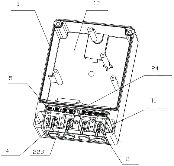
[0003] In order to solve the problem that the heat generated by the existing electric meter shunt in the background technology is not easy to dissipate and affect the measurement accuracy, the present invention provides an electric meter housing and electric meter

Method used


Image

  • Ammeter housing and ammeter
  • Ammeter housing and ammeter
  • Ammeter housing and ammeter

Examples


Embodiment 1

[0024] Embodiment one: see attached Figure 1-5 As shown, an electric meter casing and an electric meter include electronic components, a case cover and an electric meter casing, and the electronic components are arranged in an electrical cavity 12 . The ammeter housing includes a housing housing 1, the housing housing 1 includes a wiring chamber 11 and an electrical chamber 12 for accommodating electronic components, and the wiring chamber 11 is provided with a terminal box 2 , the terminal button box 2 is provided with a shunt 3, a plurality of connection terminals 4 and a plurality of function terminals 5, the function terminals are used for tripping and pulse control, and connection slots for other functions are also reserved. Described shunt 3 is located at the rear of connecting terminal 4 (see attached figure 1 , close to the terminal is the front, and close to the electrical cavity is the rear), the shunt 3 is provided with a wire 31 passing through the terminal box ...

Embodiment 2

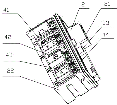
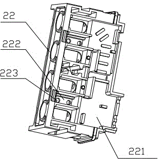
[0028]Embodiment two: see attached figure 1 , 6 , 7, the terminal block 4 includes a first terminal 41, a second terminal 42, a third terminal 43 and a fourth terminal 44, and the terminal block 6 includes a connection with the first terminal 41, the second terminal 42, the third terminal The terminal 43 and the fourth terminal 44 correspond to the first wiring board 61, the second wiring board 62, the third wiring board 63 and the fourth wiring board 64 respectively, and the first wiring board 61 and the second wiring board 62 are connected by shunting The device 3 is connected, and the third wiring board 63 and the fourth wiring board 64 are connected. The third wiring board 63 and the fourth wiring board 64 are connected through a horizontal wiring board 66, and the third wiring board 63, the horizontal wiring board 66, and the fourth wiring board 64 are of an integrated structure, and there are Insert the wires into the electrical cavity. Such a structure makes wiring ...


PUM


Abstract

The invention discloses an ammeter housing and an ammeter, for solving the problems of difficult dissipation of heat generated by a conventional ammeter shunt and affected measuring precision. The ammeter comprises electronic components, a cover and the ammeter housing. The ammeter housing comprises an accommodation housing, the accommodation housing comprises a wiring cavity and an electric appliance cavity for accommodating the electronic components, the wiring cavity is internally provided with a terminal box, the terminal box is internally provided with a shunt, multiple wiring terminals and multiple function terminals, the shunt is arranged behind the wiring terminals, the shunt is provided with a lead wire penetrating the terminal box for connection with the electronic components in the electric appliance cavity, the terminal box comprises a base and a cover plate, the shunt is arranged on the base, and the base and the cover plate cooperate to form an accommodation isolation cavity for isolating the shunt from the electric appliance cavity. The ammeter housing and the ammeter have the advantages of simple structure, convenient assembling, good heat dissipation performance, high measuring accuracy, reliable wiring, small energy consumption, low fault rate and the like.

Description

technical field [0001] The invention relates to an electric meter, in particular to an electric meter shell and the electric meter. Background technique [0002] The electric meter is the abbreviation of the electric energy meter, which is used to Measurement Electric energy meters, also known as watt-hour meters, fire meters. The upper cover and base of the existing electric meter terminal box have many and complicated processing procedures, which are not easy to automate and simplify the process; the integrated structure is lower than the waterproof level, it is difficult to meet the waterproof level of IP54 or higher, and it is easy to seep water. In addition, the existing terminal box divides the ammeter case into two accommodating chambers. The shunt and the ammeter function module are sealed in one chamber (in the electrical chamber), and the wiring terminals are in the other chamber (in the wiring chamber). During installation, the shunt is welded on the connection ...

Claims


Application Information

Patent Timeline
Patent Type & Authority Applications(China)
IPC IPC(8): G01R11/04
Inventor 黄余光
Owner WENZHOU WANXING ELECTRIC
Learn More