

Laser light emitting device, light source and projection display system
A light-emitting device and laser technology, applied in projection devices, optics, optical components, etc., can solve the problems of insufficient compact structure and high space requirements, and achieve the effect of small space and small etendue
- Summary
- Abstract
- Description
- Claims
- Application Information
AI Technical Summary
Problems solved by technology
Method used
Image

Examples
Embodiment Construction
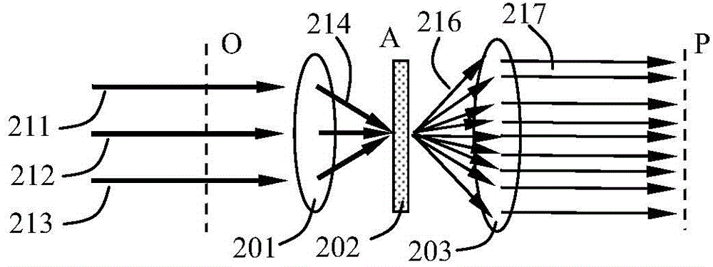
[0020] The present invention proposes a laser light emitting device, the structural schematic diagram of the first embodiment is as follows Figure 2A shown. The laser light-emitting device includes multiple lasers (not shown in the figure) for emitting parallel multiple laser beams 211, 212, 213, and also includes a focusing lens 201 for combining parallel multiple laser beams 211, 212, 213 is focused to form a light cone 214 . The focusing lens 201 may be a single lens or a lens group, which is not limited here. The laser light emitting device also includes a light scattering element 202 located at the rear end of the optical path of the focusing lens 201. The scattering angle of the light scattering element 202 is not less than two-thirds of the maximum angle between adjacent laser beams after focusing.
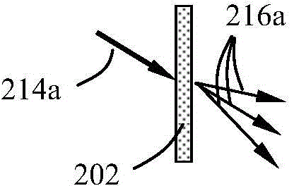
[0021] First, it is necessary to explain the two concepts of the maximum angle between adjacent laser beams and the scattering angle of the light scattering element. Su...
PUM
 Abstract
Description
Claims
Application Information