Hinge mechanism and panel apparatus

A hinge mechanism and technology on the back side, applied in the field of panel devices, can solve the problems of poor operability and large operating force, etc.

Active Publication Date: 2015-08-12
MITSUBISHI ELECTRIC CORP
View PDF7 Cites 6 Cited by
  • Summary
  • Abstract
  • Description
  • Claims
  • Application Information

AI Technical Summary

Problems solved by technology

[0014] The holding force T2 of this click function is several times the holding force T1 of the panel unit at any angle,

Method used


Image

  • Hinge mechanism and panel apparatus
  • Hinge mechanism and panel apparatus
  • Hinge mechanism and panel apparatus

Examples


Embodiment approach 1

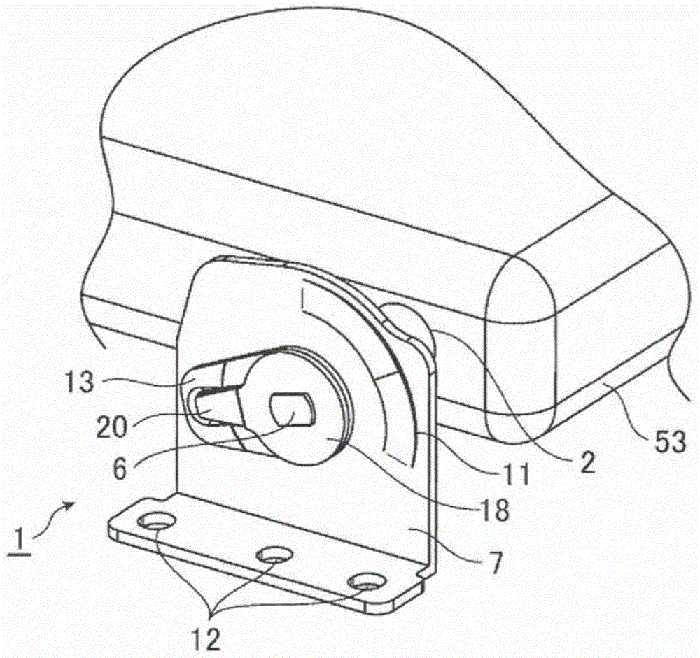
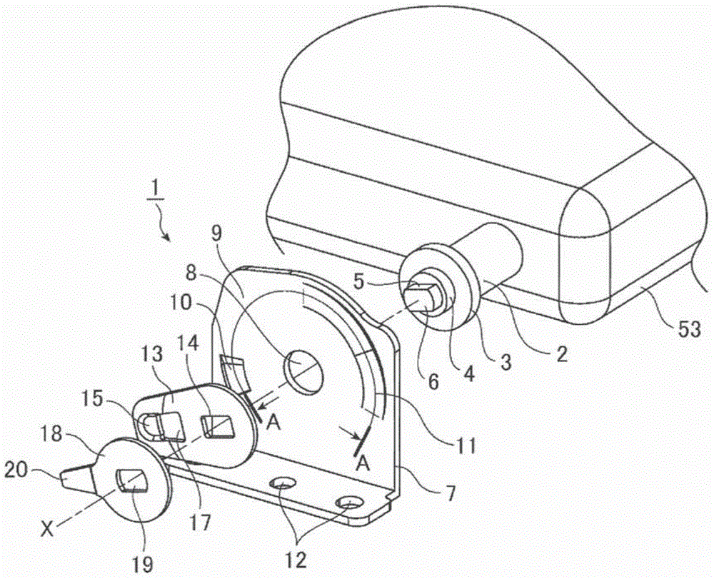
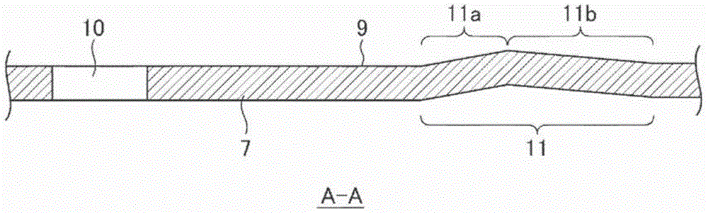
[0046] figure 1 It is an external perspective view showing the structure of the hinge mechanism 1 according to the first embodiment, figure 2 It is an exploded perspective view. image 3 is along figure 2 A cross-sectional view obtained by cutting the housing (fixed part) 7 along the line A-A shown. In Embodiment 1, a case where the hinge mechanism 1 is applied to a vehicle-mounted seatback display device (panel device) will be described as an example. Figure 4 It shows the state where the panel unit (rotating member) 53 of the seatback display device 51 to which the hinge mechanism 1 is applied is accommodated in the main body unit (fixing member) 52, Figure 5 It shows the state where the panel unit 53 is rotated to and held at the viewing position.

[0047] like Figure 4 and Figure 5 As shown, a seatback display device 51 is provided on the back of a reclining seat 50 such as a driver's seat and a passenger seat of an automobile. The seatback display device 51 i...

Embodiment approach 2

[0082] Figure 11 It is an external perspective view showing the structure of the hinge mechanism 1 according to the second embodiment, Figure 12 It is an exploded perspective view. Figure 13 is along Figure 12 The sectional view obtained by cutting the housing 7 with the D-D line shown, Figure 14 It is a cross-sectional view cut along line E-E. Figure 15 It is a front view of the click plate 13 and the friction plate 18. for Figure 11 to Figure 15 neutralize Figure 1 to Figure 9 The same or corresponding parts are marked with the same reference numerals, and descriptions are omitted. The case where the hinge mechanism 1 according to the second embodiment is applied to the seatback display device 51 will be described as an example. Figure 4 and Figure 5 .

[0083] like Figure 11 and Figure 12 As shown, the hinge mechanism 1 involved in Embodiment 2 includes: the shaft 2 fixed to the panel unit 53; the housing 7 fixed to the main body unit 52; the ring-sha...

Embodiment approach 3

[0102] Figure 19 It is an external perspective view showing the structure of the hinge mechanism 1 according to the third embodiment, Figure 20 It is an exploded perspective view. for Figure 19 and Figure 20 neutralize Figure 11 ~ Figure 17 The same or corresponding parts are marked with the same reference numerals, and descriptions are omitted. The case where the hinge mechanism 1 according to Embodiment 3 is applied to the seatback display device 51 will be described as an example. The seatback display device 51 follows the Figure 4 and Figure 5 .

[0103] like Figure 19 and Figure 20 As shown, a sliding convex portion 40 that presses and slides the housing 7 protrudes on the inner peripheral side of the ring arm 31b. Therefore, the force for holding the panel unit 53 can be increased without enlarging the size of the hinge mechanism 1 or increasing the number of parts by utilizing the sliding resistance generated when the sliding protrusion 40 slides on th...


PUM


Abstract

In a state wherein a protruding section (15) of a click plate (13) is holding a panel unit (53) at a storing angle by being fitted in a recessed section (10) of a bracket (7), the rear side of the protruding section (15) and a pressing piece (20) of a friction plate (18) are not in contact with each other, and merely a reaction force of the click plate (13) becomes resistance. When the panel unit (53) starts to rotate, the protruding section (15) moves out from the recessed section (10), and is brought into contact with the pressing piece (20) due to elastic deformation generated when the protruding section moved onto a sliding surface (9), and after the protruding section and the pressing piece are brought into contact with each other, sliding resistance is obtained by means of a reaction force between the click plate (13) and the friction plate (18).

Description

technical field [0001] The present invention relates to a hinge mechanism for holding a rotating member at an arbitrary angle with respect to a fixed member, and a panel device for holding a panel unit at an arbitrary angle with respect to a main body unit using the hinge mechanism. Background technique [0002] As a hinge mechanism that rotates a panel unit having a display and holds it at an arbitrary angle with respect to the main body unit, there is a tilt hinge described in Patent Document 1, for example. The tilt hinge includes: a mounting member having a bearing plate; a rotating shaft rotatably supported by a bearing hole provided in the bearing plate; The first friction plate and the first friction washer that are installed between the parts and the rotation shaft is inserted; the second friction plate that is in contact with the other side of the bearing plate and the rotation shaft is inserted. a friction plate and a second friction washer; a fixed washer that is...

Claims


Application Information

Patent Timeline
IPC IPC(8): F16C11/04
CPCB60R2011/0082B60R2011/0015B60R11/0235B60R2011/0085F16M11/10F16M13/02B60N3/004E05D11/082E05D2011/085H05K5/0017H05K5/0226
Inventor 永见哲郎
Owner MITSUBISHI ELECTRIC CORP
Why Eureka
Try Eureka