Process device for coating denitration catalyst slurry

The technology of denitration catalyst and process device is applied in the field of production process device of coating slurry, which can solve the problems of high cost, low production efficiency and high working intensity, and achieve the effects of reducing strength, improving efficiency and simple structure.

Active Publication Date: 2015-08-19
宁波德普福斯特环保科技有限公司
View PDF9 Cites 4 Cited by
  • Summary
  • Abstract
  • Description
  • Claims
  • Application Information

AI Technical Summary

Benefits of technology

This invention relies about an apparatus that can produce coatings on hollow ceramic carriers without having these drawbacks or other problems associated with manually applying them during manufacturing processes. It allows for more efficient use of materials while reducing their cost compared to traditional methods like dip-coat techniques.

Problems solved by technology

This patented technical problem addressed in this patents relates to improving the quality control (QC) process for producing diesel engine emissions reduction systems used in vehicles without increasing their costs or requiring more laborious steps during assembly processes. Current methods involve hand painting and baking techniques which require multiple handling stages at different temperatures before final product formation can be achieved.

Method used


Image

  • Process device for coating denitration catalyst slurry
  • Process device for coating denitration catalyst slurry
  • Process device for coating denitration catalyst slurry

Examples


Embodiment Construction

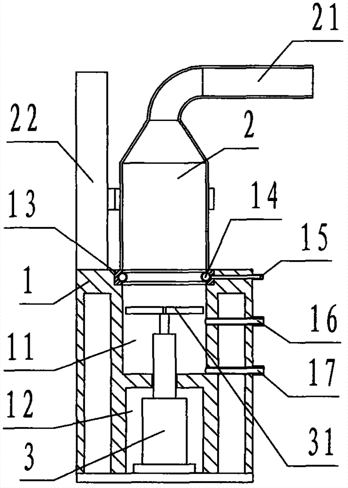
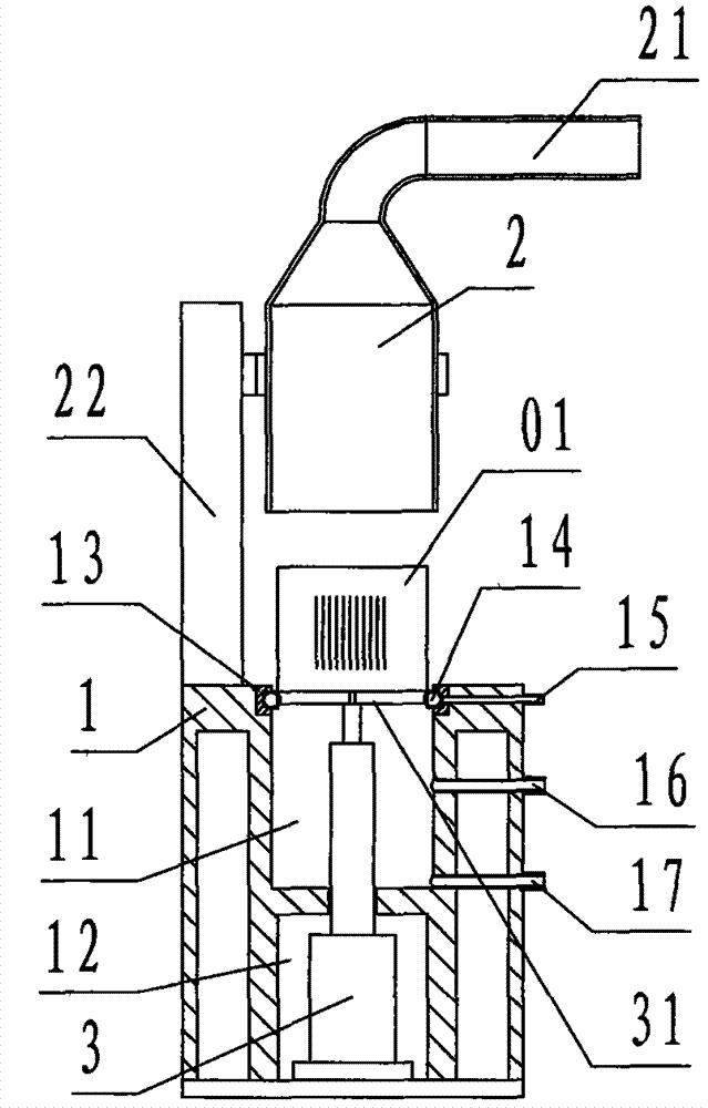
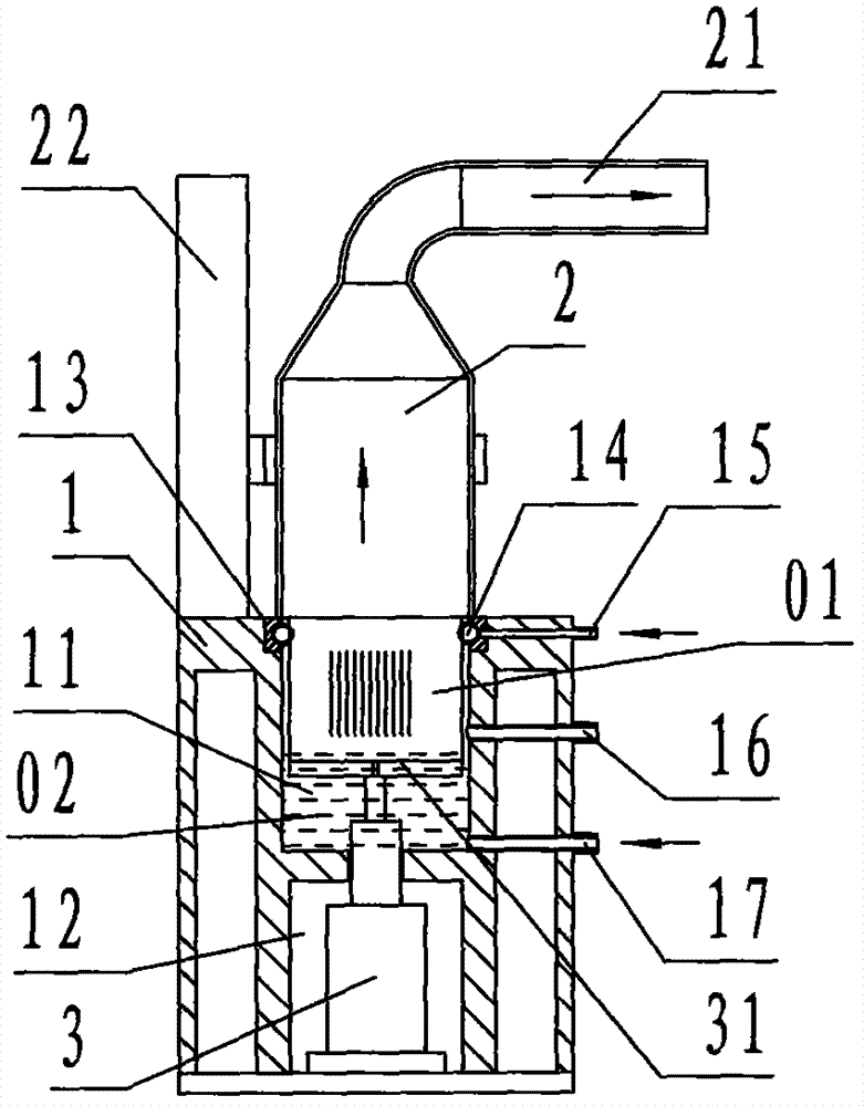
[0025] refer to Figure 1 to Figure 6 , a process device for coating denitrification catalyst slurry of the present invention includes a base 1, a gas cover 2, and a cylinder 3, wherein: the base 1 is a rectangular steel platform, and the center of the base 1 is provided with Two cylindrical hollow chambers that are isolated from each other up and down, the chamber on the top of the base 1 is called the upper chamber 11, and the chamber on the bottom of the base 1 is called the lower chamber 12; the upper chamber 11 The top is open, and the center of the bottom surface of the upper chamber 11 is provided with a round hole communicating with the lower chamber 12, which is called a piercing hole, and the upper edge of the upper chamber 11 is provided with a sealing ring 13 of a cylindrical annular polyurethane elastomer. , the inner circular side wall of the sealing ring 13 is embedded with a circular, hollow circular, rubber expansion and contraction ring 14; from top to bottom...


PUM


Abstract

The invention discloses a process device for coating denitration catalyst slurry. The process device comprises a substrate (1), an air hood (2) and an air cylinder (3). The substrate adopted by the process device is provided with an upper cavity and a lower cavity; a seal ring and an expansion contraction ring are arranged on the upper edge of the upper cavity; a lower air connector, an exhaust connector and a slurry connector are arranged at the upper part of the substrate, wherein the lower air connector is communicated with the expansion contraction ring, the exhaust connector is communicated with the middle part of the upper cavity, and the slurry connector is communicated with the lower part of the upper cavity; the air hood is provided with an upper air connector and a lifter, the air hood is positioned above the substrate, and the lifter is fixed on the substrate; the air cylinder is positioned in the lower cavity, and a piston rod of the air cylinder is connected with a support and is positioned in the upper cavity; during working, the technical scheme that firstly vacuum is utilized for absorbing slurry to the upper end face of a honeycomb carrier from downwards to upwards along honeycomb-shaped micropores and then compressed air is utilized for blowing the slurry away from the honeycomb carrier from upwards to downwards along the honeycomb-shaped micropores is adopted to complete coating, the production of honeycomb carrier coated slurry is realized, and the purposes of improving the working condition, alleviating the strength, eliminating the waste, improving the efficiency and reducing the cost are achieved.

Description


Claims


Application Information

Patent Timeline
Owner 宁波德普福斯特环保科技有限公司
Why Eureka
Try Eureka