Feeding device

A feeding device and coil material technology, applied in the direction of feeding device, positioning device, storage device, etc., can solve the problems of stamping failure, heavy weight, and inconvenient handling, so as to reduce labor force, improve production and processing performance, facilitate handling and The effect of repositioning

Inactive Publication Date: 2015-08-19
新昌县澄潭镇苗平机械厂
View PDF0 Cites 2 Cited by
  • Summary
  • Abstract
  • Description
  • Claims
  • Application Information

AI Technical Summary

Problems solved by technology

[0002] A punching machine is a stamping press. In national production, the stamping process saves materials and energy compared with traditional machining, has high efficiency, does not require high technical requirements for operators, and can be machined through various mold applications. The advantages of products that cannot be achieved, so its use is becoming more and more extensive; and the feeding device is a device for conveying materials during the stamping work of the punch press. The traditional feeding device generally includes a frame and Coiler and the strip material wound on the coiler, the coiler can rotate around the rotating shaft, when the punching press is working, the roller conveying device on the punching machine will roll the strip material wound on the coiler The material is conveyed to the stamping position of the punch press, and the coiler can be driven and rotate around the shaft. Since the coiler is driven to rotate, the requirements for the roller conveying device are relatively high, and there must be a large pulling force to pull the strip coil. Once the pulling force is insufficient or slips, the strip coil at the punching place of the punching machine cannot be kept up synchronously, resulting in punching failure; When there is a strip material, the weight is relatively large, and it is inconvenient to adjust the position and distance between the feeding device and the punching machine, so there is still room for improvement

Method used


Image

  • Feeding device

Examples


Embodiment Construction

[0010] Below in conjunction with accompanying drawing, the present invention will be further described:

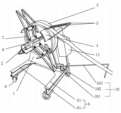
[0011] A feeding device, comprising a machine base 1, on which a rotating shaft 2 and a coiler for coiling a strip material are arranged, the rotating shaft 2 and the coiler are arranged coaxially, and the coiler includes a fixed stop Plate 3 and some movable baffles 4 that can be wound around the strip coil, the movable baffle 4 is provided with a retaining strip 5 that can limit the strip coil, and the retaining strip 5 is symmetrically distributed on both sides of the strip coil, The base 1 is provided with an underframe 8, and under the underframe 8 is provided with a roller 9. The base 1 is provided with a feeding induction device 10 and a stepping motor 11 linked with the rotating shaft 2. The feeding induction device 10 and the stepping motor 11 Electrical connections.

[0012] By adopting the above-mentioned technical scheme, the machine base 1 is provided with a ...


PUM


Abstract

The invention relates to a feeding device. The feeding device is characterized in that a winding device comprises a fixed baffle and a plurality of movable baffles which can be used for winding a strip coil; the two sides of the strip coil on the movable baffles are provided with stopping strips capable of limiting the strip coil; a bottom frame is arranged at the bottom of a base; rolling wheels are arranged under the bottom frame; the base is provided with a feeding induction device and a stepping motor which is linked with a rotary shaft; and the feeding induction device is electrically connected with the stepping motor and comprises a connection plate fixed on the base and a contact rod which is obliquely arranged relative to the connection plate. With the adoption of the technical scheme, the transportation and the position adjustment of the feeding device are facilitated and the labor force in an equipment transportation and regulation process is greatly alleviated; the strip coil can be initiatively conveyed and the influences on a punching process, caused by the fact that materials are not fed in time, are avoided; and the production and machining performances of the device are effectively improved.

Description

technical field [0001] The invention relates to a feeding device. Background technique [0002] A punching machine is a stamping press. In national production, the stamping process saves materials and energy compared with traditional machining, has high efficiency, does not require high technical requirements for operators, and can be machined through various mold applications. The advantages of products that cannot be achieved, so its use is becoming more and more extensive; and the feeding device is a device for conveying materials during the stamping work of the punch press. The traditional feeding device generally includes a frame and Coiler and the strip material wound on the coiler, the coiler can rotate around the rotating shaft, when the punching press is working, the roller conveying device on the punching machine will roll the strip material wound on the coiler The material is conveyed to the stamping position of the punch press, and the coiler can be driven and r...

Claims


Application Information

Patent Timeline
Patent Type & Authority Applications(China)
IPC IPC(8): B21D43/04B21C47/18B21C47/28B21C51/00
CPCB21D43/02B21C47/18B21C47/28
Inventor 周晓平
Owner 新昌县澄潭镇苗平机械厂
Why Eureka
Try Eureka