Annular part grinding fixture

A ring-shaped part, grinding technology, applied in the direction of grinding workpiece support, etc., can solve the problems of easy deformation, difficult to guarantee machining accuracy, poor rigidity, etc., and achieve the effect of reducing clamping deformation, high centering accuracy, and simple structure

Inactive Publication Date: 2015-08-19
CHENGDU YUNLI MACHINERY
View PDF0 Cites 5 Cited by
  • Summary
  • Abstract
  • Description
  • Claims
  • Application Information

AI Technical Summary

Problems solved by technology

[0002] Due to the poor rigidity of thin-walled ring parts, it is easy to deform if clamped by a three-jaw chuck during processing, and the processing accuracy is difficult to guarantee

Method used


Image

  • Annular part grinding fixture

Examples


Embodiment Construction

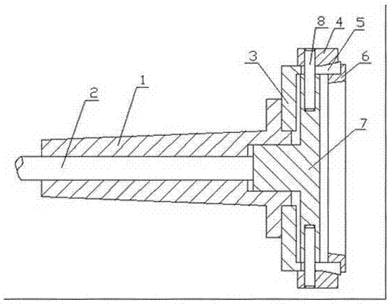
[0009] The present invention will be further described below in conjunction with the accompanying drawings.

[0010] refer to figure 1 , is a grinding fixture for ring parts, including a hollow taper shaft 1, an outer taper sleeve 3, an inner taper sleeve 4 and a push plate 7, one end of the outer taper sleeve 3 is provided with an outer taper surface, and one end of the inner taper sleeve 4 is provided with There is an inner cone surface, the inner cone sleeve 4 is set on the outer surface of the outer cone sleeve 3, the outer cone surface of the outer cone sleeve 3 matches the inner cone surface of the inner cone sleeve 4, and the outer cone sleeve 3 is fixedly connected with the taper shaft 1 , the inner tapered sleeve 4 is fixedly connected with the push plate 7, the push plate 7 is arranged in the outer tapered sleeve 3, and the outer tapered sleeve 3 is provided with a plurality of axial openings 5 ​​along the circumferential direction; the openings 5 ​​are arranged alon...


PUM


Abstract

An annular part grinding fixture comprises a taper handle shaft of hollow structure, an outer taper shaft, an inner taper shaft and a pushing disc. An outer taper face is arranged at one end of the outer taper sleeve, and an inner taper face is arranged at one end of the inner taper sleeve; the outer surface of the outer taper sleeve is sleeved with the inner taper sleeve, and the outer taper face of the outer taper sleeve is matched with the inner taper face of the inner taper sleeve; the outer taper sleeve is fixedly connected with the taper handle shaft, and the inner taper sleeve is fixedly connected with the pushing disc; and the pushing disc is arranged in the outer taper sleeve, and a plurality of axial opening gaps are formed in the outer taper sleeve in the circumferential direction. The annular part grinding fixture is simple in structure, convenient to use, capable of achieving automatic centering, and high in centering precision; and clamping force is controlled, so that clamping deformation can be reduced, and the machining precision is ensured.

Description

technical field [0001] The invention relates to a grinding fixture, in particular to an auxiliary clamping grinding fixture for annular thin-walled parts. Background technique [0002] Due to the poor rigidity of thin-walled ring parts, it is easy to deform if clamped by a three-jaw chuck during processing, and the processing accuracy is difficult to guarantee. Contents of the invention [0003] The present invention solves the above technical problems and provides a ring part grinding fixture with simple structure, high positioning accuracy and effective reduction of clamping deformation. [0004] In order to solve the above-mentioned technical problems, the present invention adopts a ring-shaped part grinding fixture, which includes a hollow taper shank, an outer taper sleeve, an inner taper sleeve and a push plate. One end of the outer taper sleeve is provided with an outer taper surface, so that One end of the inner cone sleeve is provided with an inner cone surface, ...

Claims


Application Information

Patent Timeline
Patent Type & Authority Applications(China)
IPC IPC(8): B24B41/06
CPCB24B41/067
Inventor 王强赵逢荣
Owner CHENGDU YUNLI MACHINERY
Why Eureka
Try Eureka