Robot hand-eye calibration method based on non-minimized and non-optimized algorithm

A technology of robot hand and calibration method, which is applied in the direction of manipulators and manufacturing tools, and can solve problems such as unsuitable hand-eye calibration and errors

Active Publication Date: 2015-08-19
SHANDONG UNIV
View PDF7 Cites 16 Cited by
  • Summary
  • Abstract
  • Description
  • Claims
  • Application Information

AI Technical Summary

Problems solved by technology

When performing online hand-eye calibration, the motion of the robot is determined by the specific application, not specifically designed for hand-eye calibration, so the motion data collected when the robot is moving may not be suitable for hand-eye calibration
In addition, if the rotation angle is too small or the translation is too large during the sampling movement, or the angle between the rotation axes of the two movements is too small, it will cause a large error in the final calibration result.

Method used


Image

  • Robot hand-eye calibration method based on non-minimized and non-optimized algorithm
  • Robot hand-eye calibration method based on non-minimized and non-optimized algorithm
  • Robot hand-eye calibration method based on non-minimized and non-optimized algorithm

Examples


Embodiment Construction

[0091] The present invention will be further described below in conjunction with the accompanying drawings and embodiments.

[0092] A non-minimization optimization

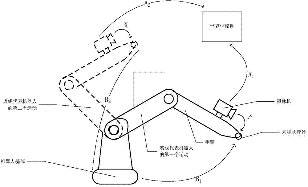
[0093] system such as figure 1 As shown, the robot base is connected with the robot arm through the first rotation axis, and the robot arm includes the first section arm and the second section arm connected by the second rotation axis, the end of the second section arm is attached with an end effector, and the end execution A camera is fixed on the device. The robot moves through the arm, the end effector moves to the corresponding position, and the base remains fixed during the movement.

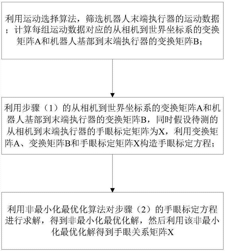
[0094] Such as figure 2 as shown,

[0095] 1. Determine the transformation matrix A from the camera to the world coordinate system i and the transformation matrix B from the base of the robot to the end effector i .

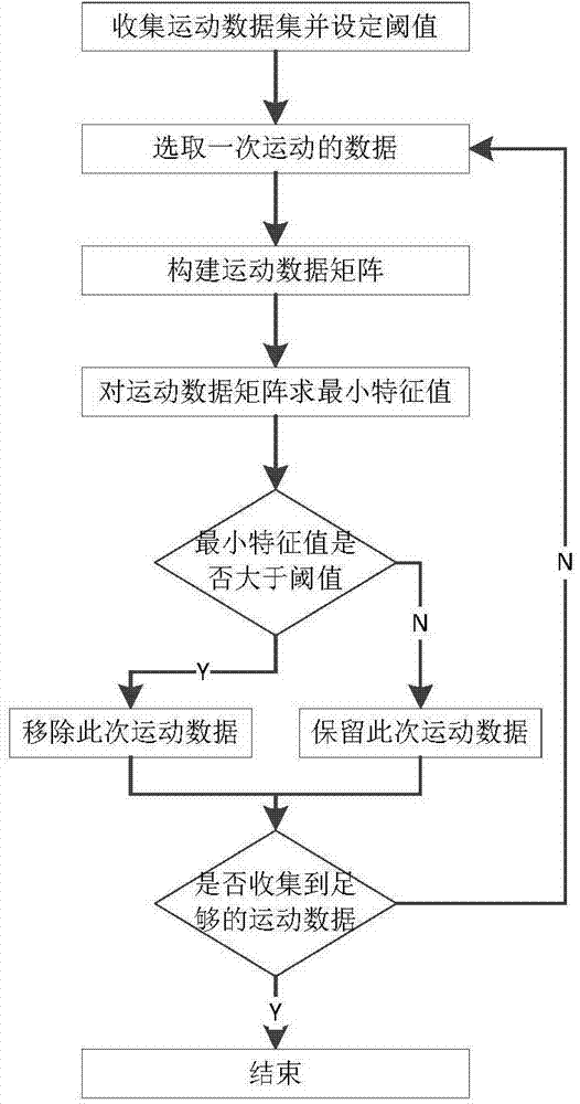
[0096] 1) Use the motion selection algorithm to select N motions of the robot end effector;

[0097] ...


PUM


Abstract

The invention discloses a robot hand-eye calibration method based on a non-minimized and non-optimized algorithm. The method is based on the non-minimized and non-optimized algorithm, calibration can be implemented by feature value calculation, and an initial value does not need to be set. The robot hand-eye calibration method comprises the following steps of selecting suitable hand-eye movement data by using a movement selection algorithm; and performing the non-minimized and non-optimized algorithm, namely, establishing a linear equation of a hand-eye calibration system by using a tensor product to obtain an optimized cost equation and solving an optimal solution of a feature matrix (y) by feature value calculation. By the robot hand-eye calibration method, feature value calculation replaces the traditional 2-norm computing, calculated amount is reduced, and problems caused by improper selection of the initial value are avoided. In a noise environment, rotation errors and translation errors of the method can meet ordinary application requirements.

Description

technical field [0001] The invention relates to a robot hand-eye calibration method based on a non-minimization optimization algorithm, relates to the technical field of industrial robot vision calibration, and can be used in technical fields such as robot surgery. Background technique [0002] Robot hand-eye calibration is a fundamental problem in machine vision. The specific operation of the robot is mainly completed by the end effector located in the last section of the robot arm. The end effector is also the "hand" of the robot. In order to position the operation of the robot, a camera is usually fixed on the end effector as The "eye" of a robot. Generally speaking, the camera can only shoot the object opposite the lens, but not the end effector where it is located. Therefore, the position of the robot hand cannot be determined by direct shooting with the camera. Robot hand-eye calibration is to measure the relative position and orientation relationship between the cam...

Claims


Application Information

Patent Timeline
IPC IPC(8): B25J19/00
Inventor 赵子健李冰清
Owner SHANDONG UNIV
Why Eureka
Try Eureka