Compressive steel skeleton structure

A technology of skeleton structure and compressive steel bars, applied in building components, building structures, walls, etc., can solve the problems of insufficient bottom tensile strength, limited bearing strength, low tensile strength, etc., to achieve safe and simple construction, anti- The effect of improved compressive strength and not easy to fall off

Active Publication Date: 2017-01-18
HEBEI ROAD & BRIDGE GROUP
View PDF5 Cites 0 Cited by
  • Summary
  • Abstract
  • Description
  • Claims
  • Application Information

AI Technical Summary

Problems solved by technology

[0002] Steel skeletons are often used in stone curtain walls and dry-hanging stone projects. The steel skeletons used in stone curtain walls and dry-hanging stone projects are welded by channel steel and angle iron. If the solder joints are not firm, it is very May cause shedding
Moreover, the general steel skeleton has limited strength and cannot bear the load better. If only simple straight cross welding of steel bars is used, it will often cause de-welding due to excessive gravity, etc., and the tensile strength is small. After the upper part is stressed, Insufficient tensile strength at the bottom leads to poor overall bending resistance and may also cause fracture, so it cannot be better used in construction

Method used


Image

  • Compressive steel skeleton structure

Examples


Embodiment Construction

[0014] The present invention is described in further detail now in conjunction with accompanying drawing. These drawings are all simplified schematic diagrams, which only illustrate the basic structure of the present invention in a schematic manner, so they only show the configurations related to the present invention.

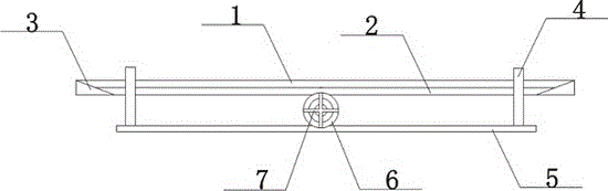
[0015] Such as figure 1 The preferred embodiment of the shown compression steel skeleton structure of the present invention comprises a top steel plate 1 and a bottom steel plate 5, and the top steel plate 1 and the bottom steel plate 5 are vertically connected with steel columns 4 near both ends, and the steel columns 4 are connected to the top layer respectively. The steel plate 1 and the bottom steel plate 5 are integrally connected. The top of the steel column 4 passes through the upper surface of the top steel plate 1 and extends outside the upper surface of the top steel plate 1. Corner guards 3 are provided near both ends of the top steel plate 1. The c...


PUM


Abstract

The invention discloses a compression reinforcement skeleton structure which comprises a top steel plate and a bottom steel plate, wherein steel columns are vertically connected with the parts, close to the two ends, of the top steel plate and the bottom steel plate; the steel columns are integrally connected with the top steel plate and the bottom steel plate respectively; the tops of the steel columns penetrate through the upper surface of the top steel plate and extend to the outer side of the upper surface of the top steel plate; angle beads are arranged at parts, close to the two ends, in the top steel plate and are in right triangle structures; the two angle beads are arranged symmetrically; a steel protection plate is connected between the two angle beads; the two ends of the steel protection plate penetrate through the two angle beads respectively and are welded with the top steel plate; and the top steel plate and the bottom steel plate is provided with a reinforcement cage located between the two steel columns. The compression reinforcement skeleton structure is safe and simple in construct; the structural strength is ensured; the skeleton structure has low possibility of falling by utilizing a welding manner, has good compression resistance, and has low possibility of bending caused by excessive pressure; the compression strength of the skeleton structure is greatly improved; and the overall strength of the structure is further improved.

Description

technical field [0001] The invention relates to a skeleton structure, in particular to a compression-resistant steel skeleton structure. Background technique [0002] Steel skeletons are often used in stone curtain walls and dry-hanging stone projects. The steel skeletons used in stone curtain walls and dry-hanging stone projects are welded by channel steel and angle iron. If the solder joints are not firm, it is very May cause shedding. Moreover, the general steel skeleton has limited strength and cannot bear the load better. If only simple straight cross welding of steel bars is used, it will often cause de-welding due to excessive gravity, etc., and the tensile strength is small. After the upper part is stressed, Insufficient tensile strength at the bottom leads to poor overall bending resistance, and may also cause fractures, so it cannot be better used in construction. Contents of the invention [0003] The technical problem to be solved by the present invention is:...

Claims


Application Information

Patent Timeline
Patent Type & Authority Patents(China)
IPC IPC(8): E04B2/88
Inventor 牛移民高长金李国威
Owner HEBEI ROAD & BRIDGE GROUP
Why Eureka
Try Eureka