System and method for determining rotor shaft position of high voltage PM AC synchronous machines using auxiliary windings

a technology of auxiliary windings and rotor shafts, which is applied in the direction of control systems, electronic commutators, starter arrangements, etc., can solve the problems of hard, or at best expensive, to implement the rotor angle estimation system described above for very high-voltage machines, and achieves a safe and accurate method, simple method, and convenient implementation.

Active Publication Date: 2016-03-15
ADVERIO PHARMA +1
View PDF12 Cites 0 Cited by
  • Summary
  • Abstract
  • Description
  • Claims
  • Application Information

AI Technical Summary

Benefits of technology

[0013]The present invention is directed to a system and method for determining rotor shaft position of a high voltage permanent magnet (PM) AC synchronous machine using auxiliary windings. The present invention solves problems associated with the prior art described above using a simple, safe and accurate method to indirectly determine the required high voltage coil flux linkages. An auxiliary set of coils is wound in the PM machine stator, co-located with a main set of stator phase windings, one auxiliary coil for each main stator coil, each auxiliary coil wound in the same magnetic configuration (the same magnetic circuit) as it's mating main stator phase coil. If the main set of stator phase coils has Nt turns in each coil, and the auxiliary set of coils have Ntx turns per coil, where Nt>>Ntx, the magnitudes of the induced voltages in the very tightly coupled auxiliary windings (very near unity coupling transformer action) are in a ratio of Ntx / Nt, a very small value, which leads to safe and easily manipulated signal level voltages, which are in direct proportion and in-phase to the voltages in the main phase windings. The required winding insulation between the high voltage main windings and the low voltage auxiliary windings is easily implemented with common winding insulation materials. Thus the auxiliary coil set can be easily and safely constructed, requiring very little winding space due to the low number of conductor turns in the auxiliary coils. And there is a second beneficial use of the auxiliary winding set, which is to economically supply isolated, low voltage power supplies for powering the signal processing and drive control electronics at remote locations of the high voltage machines, by draining very small amounts of main winding set power. This power supply function in no way compromises the primary position sensing function of the auxiliary coils (as will be detailed below).

Problems solved by technology

There are many ways to obtain rotor position information in a PM AC synchronous machine, but the most rugged and desirable measuring systems to obtain this information, particularly in harsh environments, do not utilize mechanical or optical measuring subsystems, rather, only simple voltage and current measuring instruments or transducers are employed.
The rotor angle estimation system described above is hard, or at best expensive, to implement for very high voltage machines.

Method used


Image

  • System and method for determining rotor shaft position of high voltage PM AC synchronous machines using auxiliary windings
  • System and method for determining rotor shaft position of high voltage PM AC synchronous machines using auxiliary windings
  • System and method for determining rotor shaft position of high voltage PM AC synchronous machines using auxiliary windings

Examples


Embodiment Construction

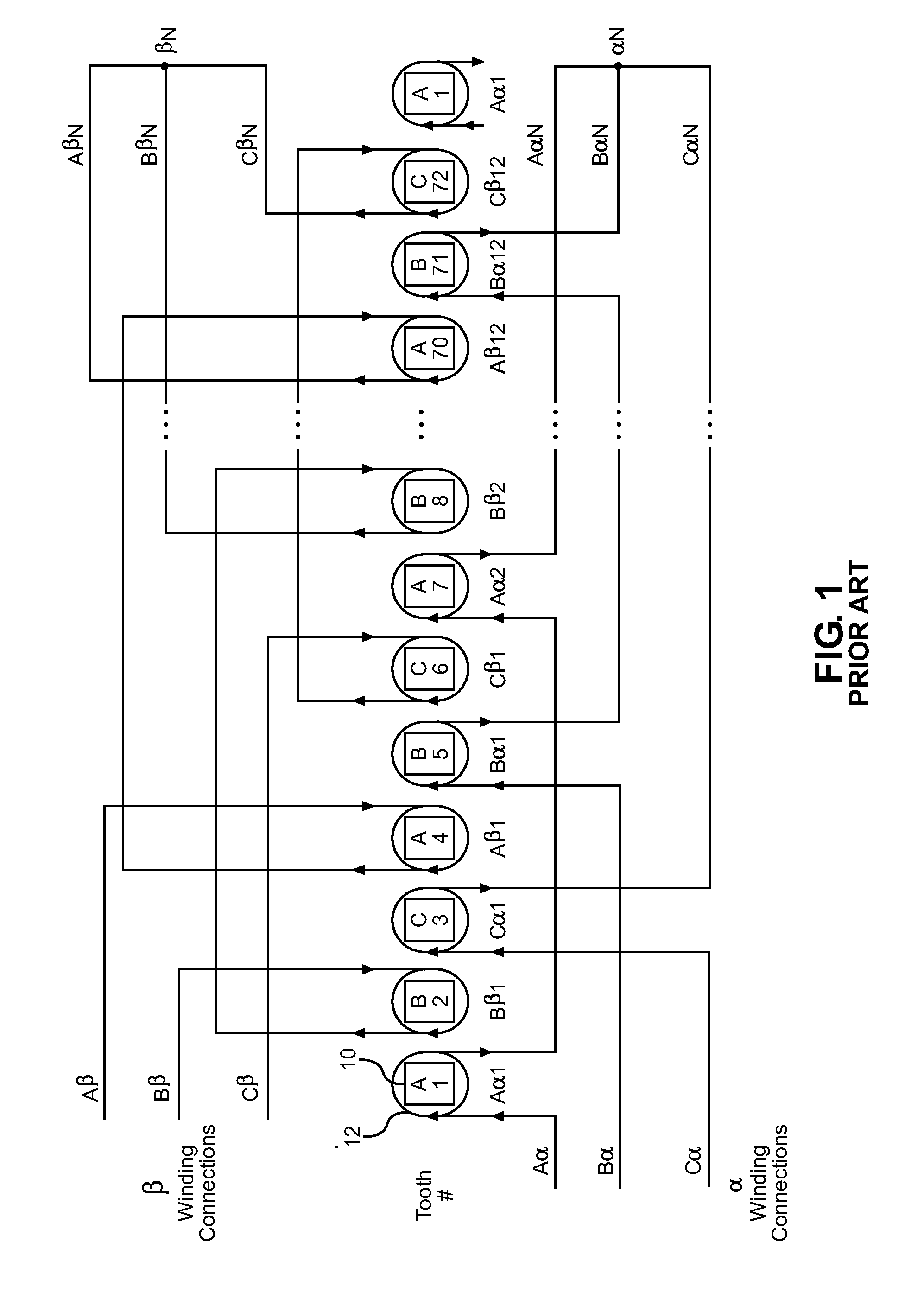
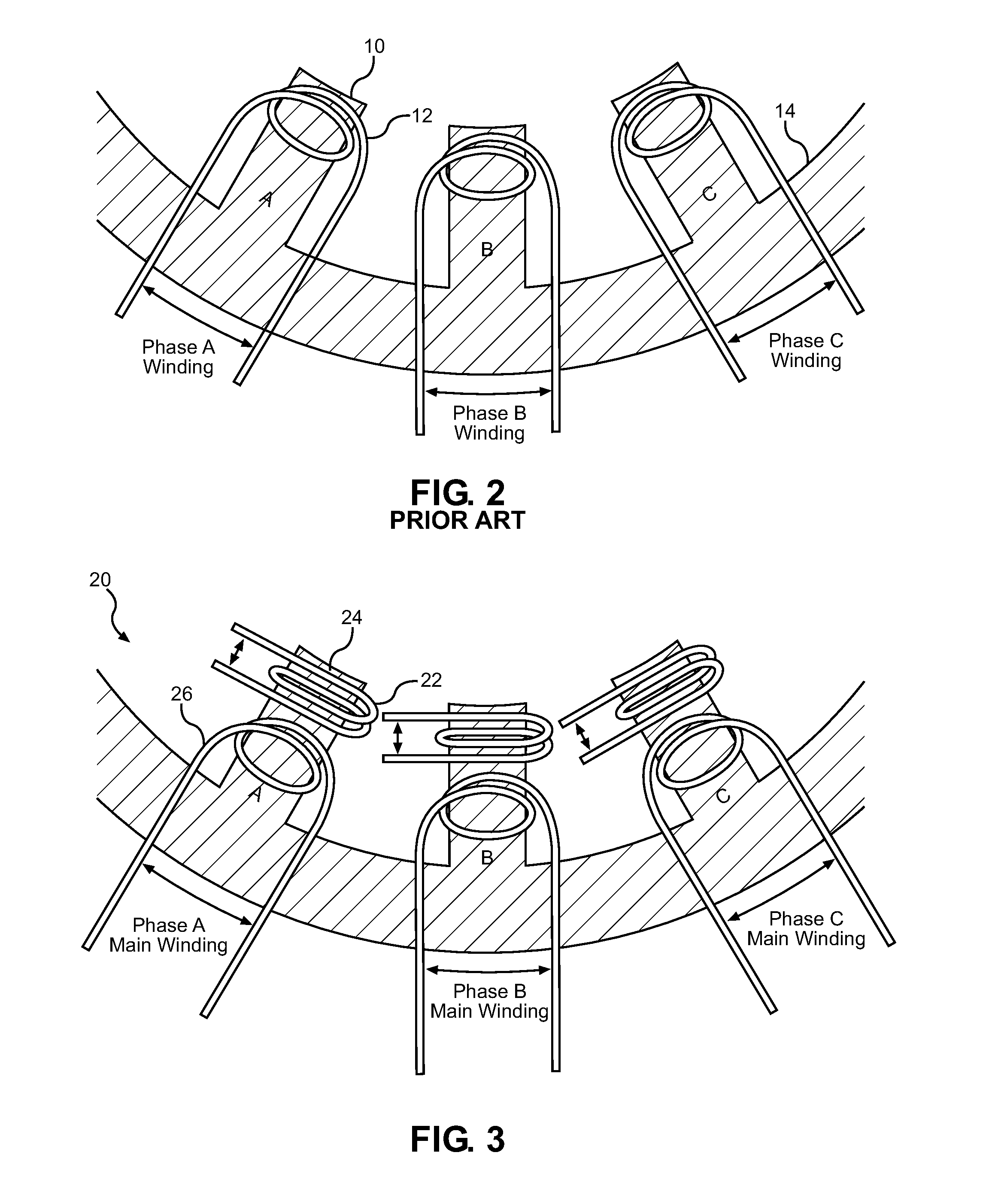
[0020]FIG. 3 shows a partial cross-sectional view of a high voltage permanent magnet (PM) AC synchronous machine 20 of the present invention. In general, the prior art machine of FIGS. 1 and 2 may be structurally modified or adapted for use with the present invention by adding a set of auxiliary phase windings 22 to each tooth 24, separate from the main coils 26, wherein the auxiliary phase windings 22 have a reduced number of turns per coil 22 than the main coils 26. The auxiliary coil set can be easily and safely constructed, requiring very little winding space due to the low number of conductor turns in the auxiliary coils 22. For the actual machine from which this example has been derived, the number of turns per coil in the auxiliary is Ntx=4 turns per coil, while the main set of coils Nt=180 turns per coil. The ratio of voltages induced per phase, auxiliary winding voltage to main winding voltage, due to the rotor magnets alone, is then 4 / 180=0.022. This much lower operating v...


PUM


Abstract

A system and method for determining rotor shaft position of high voltage permanent magnet AC synchronous machines using auxiliary windings utilizes a permanent magnet AC synchronous motor including a stator having a main set of coils and an auxiliary set of coils. A drive controller including a digital signal processor in communication with the motor utilizes a current and voltage measurements from the main and auxiliary coils to determine the position of the rotor shaft in a sensorless mode.

Description

BACKGROUND OF THE INVENTION[0001]1. Technical Field[0002]The present invention pertains to the art of permanent magnet (PM) AC synchronous machines, and more particularly, to a system and method for determining rotor shaft position of a high voltage machine using auxiliary windings.[0003]2. Background Art[0004]There are a variety of known PM AC synchronous machines or motors on the market. One example of a known PM AC synchronous machine is depicted in FIG. 1. More specifically, FIG. 1 shows machine winding details as seen from an air gap, looking toward stator teeth 10 and winding slots, of a particular three phase prior art PM machine structure. The machine depicted is a 48 pole machine with two similar sets of three concentrated phase windings per pole pair. This type of machine construction is referred to as a ½ slot per pole per phase fractional slot winding machine. Thus the 48 pole machine has 72 stator teeth / slots. The windings 12 are said to be concentrated because each win...

Claims


Application Information

Patent Timeline
Patent Type & Authority Patents(United States)
IPC IPC(8): H02P6/14H02P27/06H02P6/18H02P6/20H02P25/02
CPCH02P27/06H02P6/181H02P6/20H02P25/03H02P6/21
Inventor MCCLEER, PATRICK J.MAINS, RICHARD K.
Owner ADVERIO PHARMA
Why Eureka
Try Eureka