
Connecting apparatus of dual-wall high-pressure gas pipelines

A connection device, high-pressure gas technology, applied in flange connection, pipe/pipe joint/pipe fitting, through components, etc., can solve the problems of inconvenient installation, maintenance, dismantling and inspection, large volume, etc., to achieve compact structure, small volume, The effect of reducing the risk of leakage

Inactive Publication Date: 2015-08-19
CSSC MES DIESEL
View PDF6 Cites 10 Cited by
  • Summary
  • Abstract
  • Description
  • Claims
  • Application Information

AI Technical Summary

Problems solved by technology

[0007] The technical problem to be solved by the present invention is to overcome the shortcomings of the existing high-pressure gas double-wall pipe connection method, such as large volume, inconvenient installation and maintenance, and the risk of leakage, to provide a double-wall high-pressure gas pipe with integrated inner and outer pipes. The connecting device of the pipeline adopts an integrated structure of connecting the inner and outer pipes to make the structure of the connecting device more compact, improve the structural strength, reduce the volume, and reduce the sealing surface, so as to increase the reliability of the connection, reduce the difficulty of installation and the requirements for installation space, and improve work efficiency, etc.

Method used


Image

  • Connecting apparatus of dual-wall high-pressure gas pipelines
  • Connecting apparatus of dual-wall high-pressure gas pipelines
  • Connecting apparatus of dual-wall high-pressure gas pipelines

Examples


Embodiment Construction

[0031] Embodiments of the present invention will be described in detail below in conjunction with the accompanying drawings.

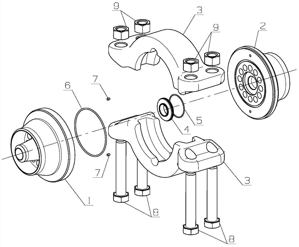
[0032] see figure 1 , the connection device of the double-wall high-pressure gas pipeline shown in the figure is connected to the double-wall high-pressure gas pipeline, including the front ventilation flange 1, the rear ventilation flange 2, a pair of Huff type ferrules 3, T-shaped sealing rings 4, Inner sealing ring 5 and outer sealing ring 6.

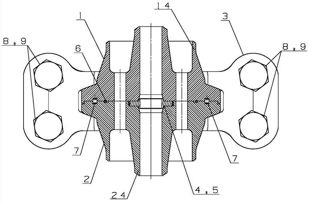
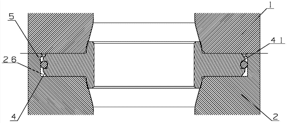
[0033] see Figure 4 , the front ventilation flange 1 is provided with a front flange inner hole 11 along the axial direction, and a plurality of front flange outer holes 12 along the axial direction are arranged around the front flange inner hole 11; the rear ventilation The flange 2 is provided with a rear flange inner hole 21 along the axial direction, and a plurality of rear flange outer holes 22 along the axial direction are arranged around the rear flange inner hole 21; The ventilation flanges 2 are ...


PUM


Abstract

The invention relates to a connecting apparatus of dual-wall high-pressure gas pipelines. The connecting apparatus comprises a front ventilation flange, a rear ventilation flange, a pair of huff type cutting sleeves, a T-shaped sealing ring, an inner sealing ring, and an outer sealing ring. Inner holes are formed in the centers of the front ventilation flange and the rear ventilation flange along the axial directions; and a plurality of outer holes are formed by encircling the inner holes along the axial direction. The huff type cutting sleeves enable the front ventilation flange and the rear ventilation flange that are in a butt joint mode to be held tightly by bolts and nuts to form an integrated structure with an inner tube and outer tubes. The inner hole of the front ventilation flange and the inner hole of the rear ventilation flange are connected to form an inner tube for conveying a main medium; and the outer holes of the front ventilation flange and the outer holes of the rear ventilation flange are connected to form outer tubes for conveying auxiliary mediums. The provided connecting apparatus having advantages of small size, convenient installation, and high connection safety and reliability and the like can be applied to fields of natural gas extraction and conveying, chemical industry, shipping industry, and aerospace and the like and can be used for realizing connection of dual-wall high-pressure gas pipelines for conveying high-pressure combustible gas or hazardous gas indoors or in an environment with poor ventilation.

Description

technical field [0001] The invention relates to a pipeline connection device for conveying high-pressure combustible gas or toxic and harmful gas indoors or in a poorly ventilated environment, in particular to a double-wall high-pressure gas pipeline connection device, which belongs to the technical field of chemical industry. Background technique [0002] With the development of international trade and shipping, the exhaust emissions of marine diesel engines fueled by petroleum products are increasingly polluting the current environment. In order to achieve energy saving and emission reduction, dual-fuel engine technology has gained more and more attention. The ship's low-speed dual-fuel engine refers to a ship's main engine that can not only use fuel oil (diesel / heavy oil) as fuel, but also gas (natural gas) as fuel. [0003] For the dual-fuel engine using the Diesel cycle, the gas used is high-pressure natural gas (30MPa), and the high-pressure natural gas is output from ...

Claims


Application Information

Patent Timeline
Patent Type & Authority Applications(China)
IPC IPC(8): F16L23/08F16L23/12F16L23/18
CPCF16L23/08F16L23/12F16L23/18
Inventor 王璞焦雷杜清
Owner CSSC MES DIESEL
Learn More