Shear box device having self-adaptive structural plane

A shear box and structural surface technology, applied in the field of rock mechanics, can solve the problems of excessive frictional resistance on the side of the specimen and the shear box, shear plane breaking or twisting, and lateral shaking of the specimen, etc. The effect of reducing the normal direction, reducing the frictional resistance, and avoiding breaking

Active Publication Date: 2015-08-19
CHINA UNIV OF MINING & TECH
View PDF6 Cites 19 Cited by
  • Summary
  • Abstract
  • Description
  • Claims
  • Application Information

AI Technical Summary

Problems solved by technology

In the current shear test, the shear box generally has a fixed shape and size, and most of the materials sampled on site need to be processed indoors or fixed by pouring. Under the influence of cutting vibration, cutter head cooling water immersion or pouring disturbance, etc., The physical and mechanical properties of the structural surface often change to a certain extent, which brings great challenges to the preparation of the specimen; if the size of the specimen is strictly consistent with the inner diameter of the shear box, during the normal loading process, due to the Lateral expansion and deformation will cause excessive friction between the specimen and the side of the shear box, so that the normal load does not fully act on the shear plane; if the size of the specimen is too small than the inner diameter of the shear box, the During the loading process, it is easy to cause the specimen to shake sideways, causing the shear surface to be broken or twisted instead of sheared, resulting in the failure of the test

Method used


Image

  • Shear box device having self-adaptive structural plane
  • Shear box device having self-adaptive structural plane
  • Shear box device having self-adaptive structural plane

Examples


Embodiment Construction

[0024] The present invention will be further explained below in conjunction with the accompanying drawings.

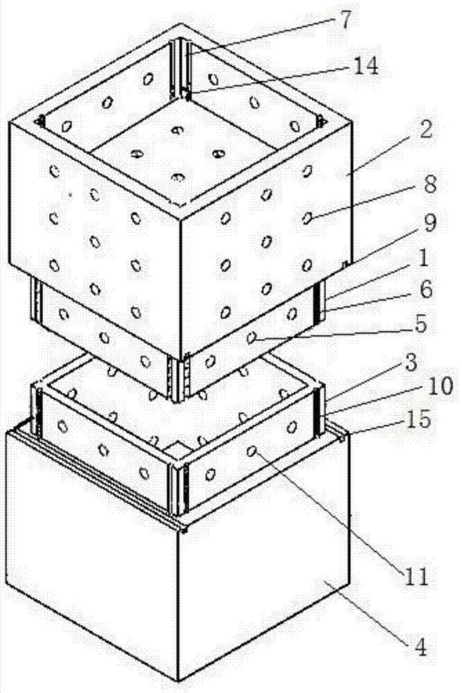
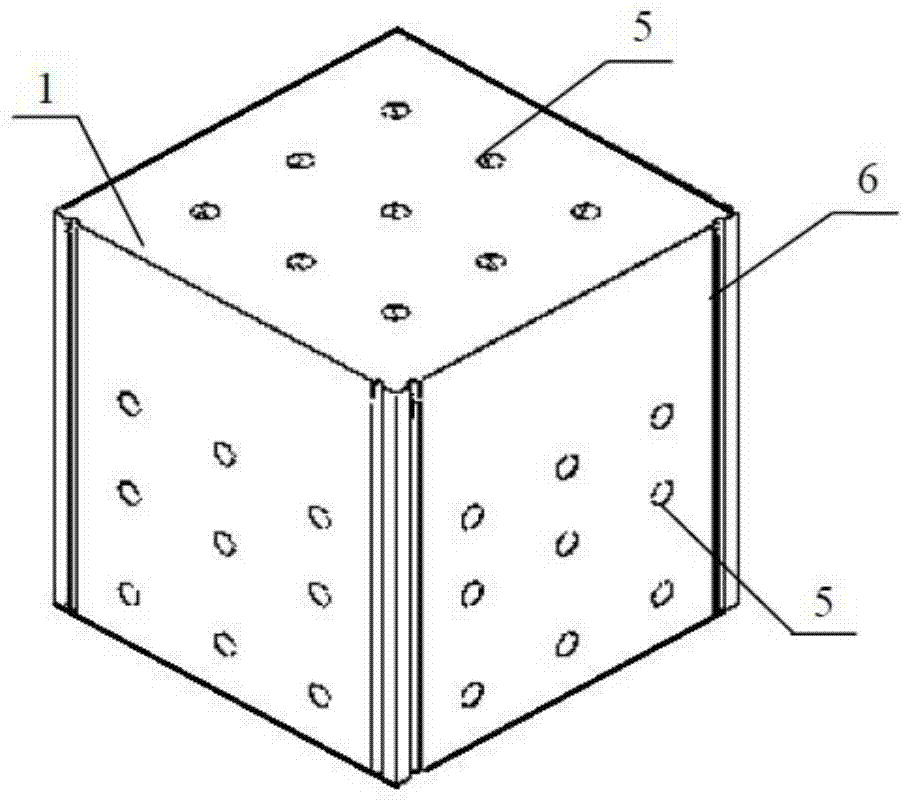
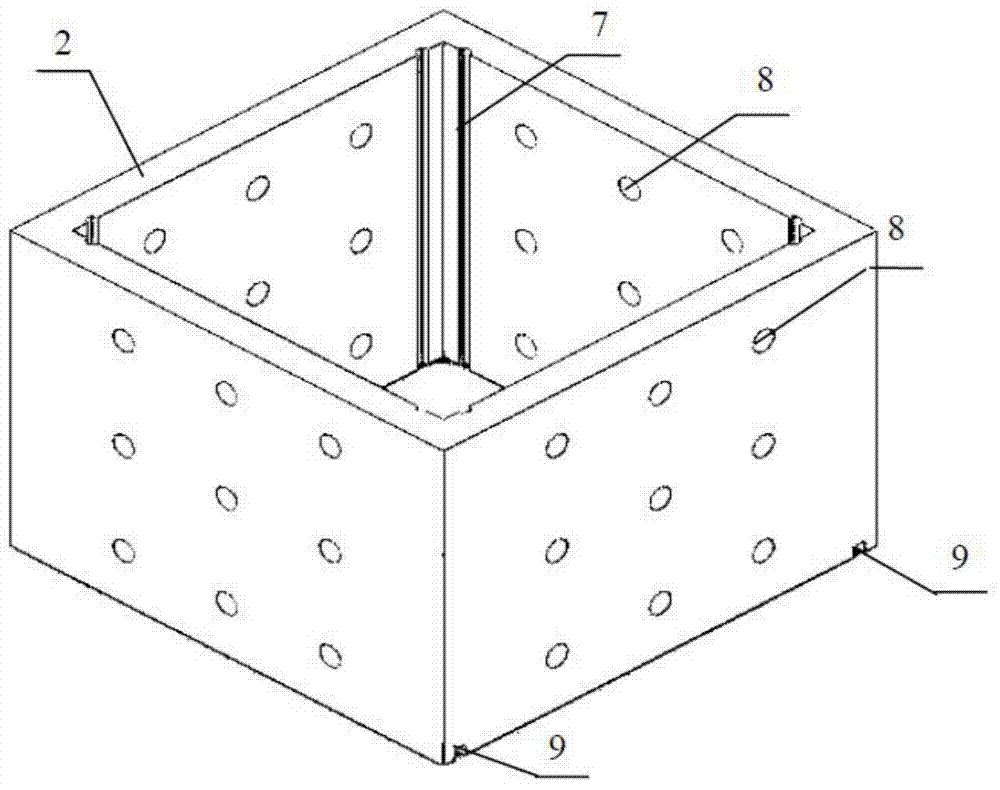
[0025] Such as Figures 1 to 9 As shown, the self-adaptive structural surface shearing box device of the present invention includes an upper shearing box and a lower shearing box, and the upper shearing box includes an upper shearing box inner box 1 and an upper shearing box outer box 2, and the upper shearing box The inner box 1 is set in the outer box 2 of the upper shear box. The cutting box inner box 3 is set in the lower cutting box outer box 4, and the lower cutting box inner box 3 is provided with a bottom cover. The inner box 1 of the upper shear box is flush with the bottom surface of the outer box 2 of the upper shear box, and the inner box 3 of the lower shear box is flush with the top surfaces of the outer box 4 of the lower shear box. The distance between the outer wall of the inner box 1 of the upper shear box and the inner wall of the outer box 2 of th...


PUM


Abstract

The invention discloses a shear box device having a self-adaptive structural plane. The shear box device comprises an upper inner shear box, an upper outer shear box, a lower inner shear box and a lower outer shear box, wherein two in-line arrangement spherical ball rows are respectively arranged between the inner side wall of the upper outer shear box and the side wall of the upper inner shear box and between the inner side wall of the lower outer shear box and the outer side wall of the lower inner shear box; an in-line arrangement cylindrical ball row phase is arranged between the top surface of the lower outer shear box and the bottom surface of the upper outer shear box; test piece fixing bolt holes are respectively formed in the upper inner shear box, the lower inner shear box and the upper outer shear box; a test piece fixing bolt and a fixed plug pin are arranged in each test piece fixing bolt hole. The shear box device can flexibly adapt to the shape and size of a field sampling test piece or an indoor homemade test piece, and can meet the requirements of the test piece for minimum disturbance and high precision test after field sampling.

Description

technical field [0001] The invention relates to a rock indoor direct shear test technology in the technical field of rock mechanics, in particular to a specimen fixing device for a structural face indoor shear test. Background technique [0002] The physical and mechanical properties of structural surfaces are one of the important factors affecting the stability of engineering rock mass, which are usually determined by indoor push shear tests. Process the sample chiseled on site into a specimen that matches the size of the shear box, pour it into the shear box, apply a normal load to the upper part of the specimen, fix the horizontal displacement of the upper shear box, and apply shear to the lower shear box. The shear load was used to cause the specimen to fail along the shear joint reserved in the middle, and to evaluate its shear strength. [0003] According to relevant national regulations, the original physical state of the structural surface should be maintained durin...

Claims


Application Information

Patent Timeline
Patent Type & Authority Applications(China)
IPC IPC(8): G01N3/24
Inventor 张强蔚立元蒋斌松曹小为吕华剑
Owner CHINA UNIV OF MINING & TECH
Why Eureka
Try Eureka